Preface Copyright This publication, including all photographs, illustrations and software, is protected under international copyright laws, with all rights reserved. Neither this manual, nor any of the material contained herein, may be reproduced without written consent of the author. Version 1.0 Disclaimer The information in this document is subject to change without notice.
Declaration of Conformity This device complies with part 15 of the FCC rules. Operation is subject to the following conditions: • This device may not cause harmful interference. • This device must accept any interference received, including interference that may cause undesired operation.
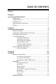
TABLE OF CONTENTS Preface i Chapter 1 1 Introducing the Motherboard 1 Introduction...................................................................................1 Pakage Contents............................................................................1 Specifications................................................................................2 Motherboard Components..........................................................4 I/O Ports.............................................................
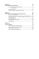
Chapter 4 77 Using the Motherboard Software 77 Auto-installing under Windows 7/8..............................................77 Running Setup.........................................................................77 Manual Installation..........................................................................79 ECS Utility Software (Intelligent EZ Utility).....................................79 Chapter 5 81 Intel® Matrix Storage Manager RAID Configuration 81 Before creating a RAID set.................
Introduction Chapter 1 Chapter 1 Introducing the Motherboard Thank you for choosing the H87H3-M4 motherboard. This motherboard is a high performance, enhanced function motherboard designed to support the LGA1150 socket for Intel® 4th Generation CoreTM Family processors. This motherboard is based on Intel® H87 Express Chipset for best desktop platform solution. It supports up to 32 GB of system memory with dual channel DDR3 1600/ 1333 MHz.
Chapter 1 Specifications CPU • • LGA1150 socket for Intel ® 4 th Generation Core TM Family processors Supports TDP up to 95W Note: Please go to ECS website for the latest CPU support list. Chipset • Intel® H87 Chipset Memory • • • Dual-channel DDR3 memory architecture 4 x 240-pin DDR3 DIMM sockets support up to 32 GB Supports DDR3 1600/1333 MHz SDRAM Note: Please go to ECS website for the latest Memory support list.
• • • • • • • • • • • AMI BIOS with 64Mb SPI Flash ROM Supports Plug and Play, STR(S3)/STD(S4), Hardware Monitor Supports ACPI & DMI Audio, LAN, can be disabled in BIOS F7 hot key for boot up devices option Supports PgUp clear CMOS Hotkey (Has PS2 KB Model only) Supports Dual/Triple Dispaly Supports Over-Clocking Supports GUI UEFI BIOS II Supports Multi-Language Supports AC’97/HD Audio auto detect (default) AP/Bundled Software Support • • ECS Exclusive AP: Supports eBLU*1/eDLU/eSF*1/EZ Charger*1 3rd Par
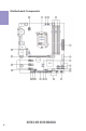
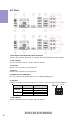
Chapter 1 4 Motherboard Components H87H3-M4 USER MANUAL
LABEL COMPONENTS 1. CPU Socket 2. PWR_FAN 3. CPU_FAN 4. DDR3_1~4 5. ATX_POWER 6. USB3F 7. ME_UNLOCK 8. SATA3_1/2 & SATA3~6 9. CIR 10. CASE 11. F_PANEL 12. F_USB1~2 13. TPM 14. CLR_CMOS 15. LPT 16. SPK 17. SPDIFO 18. F_AUDIO 19. COM 20. PCIE1~3 21. PCIEX16 22. SYS_FAN 23. ATX12V1 LGA1150 socket for Intel® 4th Generation CoreTM Family processors 3-pin Power cooling fan connector 4-pin CPU cooling fan connector 240-pin DDR3 Module slots Standard 24-pin ATX power connector Front panel USB 3.
Chapter 1 I/O Ports 1. PS/2 Mouse and Keyboard Combo Connector Use the PS/2 combo connector to connect the PS/2 Keyboard or PS/2 Mouse. 2. USB 2.0 Ports Use the USB 2.0 ports to connect USB 2.0 devices. 3. VGA Port Connect your monitor to the VGA port. 4. DVI Port Connect your monitor to the DVI port. 5. Display Port (or HDMI Port) You can connect the display device to the display/HDMI port. 6. LAN Port Connect an RJ-45 jack to the LAN port to connect your computer to the Network.
A: Center & Woofer Chapter 1 8. Audio ports Use the audio jacks to connect audio devices. The D port is for stereo line-in signal,while the F port is for microphone in signal. This motherboard supports 8channel audio devices that correspond to the A, B, C, and E port respectively. In addition, all of the 3 ports, B, C, and E provide users with both right & left channels individually.Users please refer to the following note for specific port function definition.
Chapter 1 8 Memo H87H3-M4 USER MANUAL
Chapter 2 Installing the Motherboard Follow these safety precautions when installing the motherboard: • • • • Wear a grounding strap attached to a grounded device to avoid damage from static electricity. Discharge static electricity by touching the metal case of a safely grounded object before working on the motherboard. Leave components in the static-proof bags.
2-3. Checking Jumper Settings The following illustration shows the location of the motherboard jumpers. Pin 1 is labeled. Chapter 2 To avoid the system instability after clearing CMOS, we recommend users to enter the main BIOS setting page to “Load Default Settings” and then “Save and Exit Setup”.
2-4. Installing Hardware • • • • This motherboard has an LGA1150 socket. When choosing a processor, consider the performance requirements of the system. Performance is based on the processor design, the clock speed and system bus frequency of the processor, and the quantity of internal cache memory and external cache memory. You may be able to change the settings in the system Setup Utility. We strongly recommend you do not over-clock processor or other components to run faster than their rated speed.
D. Rotate the load plate onto the package IHS (Intergraded Heat Spreader). Engage the load lever while pressing down lightly onto the load plate. Secure the load lever with the hook under retention tab. Then the cover will flick automatically. Chapter 2 Please save and replace the cover onto the CPU socket if processor is removed.
• • • • • • Install the cooling fan in a well-lit work area so that you can clearly see the motherboard and processor socket. Avoid using cooling fans with sharp edges in case the fan casing and the clips cause serious damage to the motherboard or its components. To achieve better airflow rates and heat dissipation, we suggest that you use a high quality fan with 3800 rpm at least. CPU fan and heat sink installation procedures may vary with the type of CPU fan/heatsink supplied.
2-4-3. Installing Memory Modules • • Chapter 2 • • This motherboard accommodates four memory modules. It can support four 240-pin DDR3 1600/1333 MHz. Do not remove any memory module from its antistatic packaging until you are ready to install it on the motherboard. Handle the modules only by their edges. Do not touch the components or metal parts. Always wear a grounding strap when you handle the modules. You must install at least one module in any of the four slots. Total memory capacity is 32 GB.
Recommend memory configuration Sockets DDR3_1 DDR3_2 DDR3_3 1 DIMM ~ Populated ~ DDR3_4 ~ 1 DIMM ~ ~ ~ Populated 2 DIMMs ~ Populated ~ Populated 3 DIMMs Populated Populated ~ Populated 3 DIMMs ~ Populated Populated Populated 4 DIMMs Populated Populated Populated Populated Chapter 2 Model Due to Intel CPU spec definition, please follow the table above for recommended memory configuration. 1.
2-4-4. Installing Add-on Cards The slots on this motherboard are designed to hold expansion cards and connect them to the system bus. Expansion slots are a means of adding or enhancing the motherboard’s features and capabilities. With these efficient facilities, you can increase the motherboard’s capabilities by adding hardware that performs tasks that are not part of the basic system. Chapter 2 PCIE1~3 Slots The PCI Express x1 slots are fully compliant to the PCI Express Base Specification revision 2.0.
Follow these instructions to install an add-on card: 2 3 Remove a blanking plate from the system case corresponding to the slot you are going to use. Install the edge connector of the add-on card into the expansion slot. Ensure that the edge connector is correctly seated in the slot. Secure the metal bracket of the card to the system case with a screw.
2-4-5. Connecting Optional Devices Refer to the following for information on connecting the motherboard’s optional devices: Chapter 2 18 No. Components No.
1. USB3F: Front Panel USB 3.0 Header Chapter 2 This Motherboard implements one USB 3.0 header supporting 2 extra front USB 3.0 ports, which delivers 5Gb/s transfer rate. Please make sure that the USB cable has the same pin assignment as indicated above. A different pin assignment may cause damage or system hang-up. 2 & 3. SATA3_1/2 & SATA3~6: Serial ATA Connectors SATA3_1/2 & SATA3~6 connectors are used to support the Serial ATA 6Gb/s device, simpler disk drive cabling and easier PC assembly.
4. CASE: Chassis Intrusion Detect Header This detects if the chassis cover has been removed. This function needs a chassis equipped with instrusion detection switch and needs to be enabled in BIOS. Chapter 2 5. F_USB1~2: Front Panel USB 2.0 Headers The motherboard has two USB 2.0 headers supporting four USB 2.0 ports. Additionally, some computer cases have USB ports at the front of the case. If you have this kind of case, use auxiliary USB connector to connect the front-mounted ports to the motherboard.
6. TPM: Trusted Platform Module Header Chapter 2 Trusted platform module (TPM) is a published specification detailing a microcontroller that can store secured information, and implementations of that specification. 7.
8. LPT: Onboard Parallel Port Header This is a header that can be used to connect to the printer, scanner or other devices. Chapter 2 9. SPDIFO: SPDIF Out Header This is an optional header that provides an SPDIFO (Sony/Philips Digital Interface) output to digital multimedia device through optical fiber or coaxial connector.
10. F_AUDIO: Front Panel Audio Header Chapter 2 The front panel audio header allows the user to install auxiliary front-oriented microphone and line-out ports for easier access. This header supports HD audio by default. If you want connect an AC’ 97 front panel audio to HD onboard headers, please set as below picture. AC’ 97 Audio Configuration: To enable the front panel audio connector to support AC97 Audio mode.
If you use AC’ 97 Front Panel, please don’ t tick off “Using Front Jack Detect ”. If you use HD Audio Front Panel, please tick off the option of “Using Front Jack Detect ”.
11. COM: Onboard Serial Port Header Chapter 2 Connect a serial port extension bracket to this header to add a serial port to your system. 12.
2-4-6. Installing a SATA Hard Drive This section describes how to install a SATA Hard Drive. About SATA Connectors Chapter 2 Your motherboard features six SATA connectors supporting a total of six drives. SATA refers to Serial ATA (Advanced Technology Attachment) is the standard interface for the IDE hard drives which are currently used in most PCs. These connectors are well designed and will only fit in one orientation.
2-4-7. Connecting Case Components Chapter 2 After you have installed the motherboard into a case, you can begin connecting the motherboard components. Refer to the following: No. Components No.
1 & 2 & 6. CPU_FAN (CPU Cooling FAN Connector) & PWR_FAN (Power Cooling FAN Connector) & SYS_FAN (System Cooling FAN Connector) Connect the CPU cooling fan cable to CPU_FAN. Connect the system cooling fan connector to SYS_FAN. Connect the power cooling fan connector to PWR_FAN. Chapter 2 Users please note that the fan connector supports the CPU cooling fan of 1.1A ~ 2.2A (26.4W max) at +12V. 3 & 7.
Connecting 24-pin power cable With ATX v2.x power supply, users please note that when installing 24-pin power cable, the latches of power cable and the ATX match perfectly. 24-pin power cable Chapter 2 The ATX 24-pin connector allows you to connect to ATX v2.x power supply. Connecting 4-pin power cable The ATX12V4P power connector is used to provide power to the CPU. When installing 4-pin power cable, the latches of power cable and the ATX12V4P match perfectly.
4. F_PANEL: Front Panel Header The front panel header (F_PANEL) provides a standard set of switch and LED headers commonly found on ATX or Micro ATX cases. Refer to the table below for information: Chapter 2 Hard Drive Activity LED Connecting pins 1 and 3 to a front panel mounted LED provides visual indication that data is being read from or written to the hard drive. For the LED to function properly, an IDE drive should be connected to the onboard IDE interface.
5. SPK: Speaker Header Chapter 2 Connect the case speaker cable to SPK. This concludes Chapter 2. The next chapter covers the BIOS.
Memo Chapter 2 32 H87H3-M4 USER MANUAL
Chapter 3 Using BIOS About the Setup Utility The BIOS (Basic Input and Output System) Setup Utility displays the system’s configuration status and provides you with options to set system parameters. The parameters are stored in battery-backed-up CMOS RAM that saves this information when the power is turned off. When the system is turned back on, the system is configured with the values you stored in CMOS.
Press the delete key to access BIOS Setup Utility. Main Advanced Chipset M.I.B. III System Language Security Exit Choose the system default language BIOS Information System Date System Time Boot English Wed 05/15/2013 02:05:31 Chapter 3 : Select Screen /Click: Select Item Enter/Dbl Click : Select +/- : Change Opt.
In this manual, default values are enclosed in parenthesis. Submenu items are denoted by an icon . The default BIOS setting for this motherboard apply for most conditions with optimum performance. We do not suggest users change the default values in the BIOS setup and take no responsibility to any damage caused by changing the BIOS settings. BIOS Navigation Keys The BIOS navigation keys are listed below: KEY FUNCTION Exits the current menu Scrolls through the items on a menu +/-Change Opt.
Main Menu This menu shows the information of BIOS and enables you to set the system language, date and time. Main Advanced Chipset M.I.B. III System Date System Time Security Exit Choose the system default language BIOS Information System Language Boot English Wed 05/15/2013 02:05:31 Chapter 3 : Select Screen /Click: Select Item Enter/Dbl Click : Select +/- : Change Opt.
Advanced Menu The Advanced menu items allow you to change the settings for the CPU and other system. Advanced Chipset LAN Configuration PC Health Status Power Management Setup PCI Express Configuration ACPI Settings CPU Configuration SATA Configuration Trusted Computing USB Configuration Super IO Configuration Intel(R) Rapid Start Technology Intel(R) Smart Connect Technology Intel ME BIOS Extension Configuration M.I.B.
LAN Configuration The item in the menu shows the LAN-related information that the BIOS automatically detects. Main Advanced Chipset M.I.B. III Boot LAN Configuration Onboard LAN Controller Enabled Security Exit Enabled/Disabled Onboard LAN Controller : Select Screen /Click: Select Item Chapter 3 Enter/Dbl Click : Select +/- : Change Opt.
PC Health Status On motherboards support hardware monitoring, this item lets you monitor the parameters for critical voltages, temperatures and fan speeds. Main Advanced PC Health Status Chipset M.I.B. III Boot Security Exit 48 2083 RPM 0 RPM 0 RPM 1.752V 1.512V TCC Activation Temperature (DTS) 100 : Select Screen /Click: Select Item Enter/Dbl Click : Select +/- : Change Opt.
Smart Fan Mode (Normal) This item allows you to select the fan mode (Normal, Quiet, Silent, or Manual) for a better operation environment. If you choose Normal mode, the fan speed will be auto adjusted depending on the CPU temperature. If you choose Quite mode, the fan speed will be auto minimized for quiet environment. If you choose Silent mode, the fan speed will be auto restricted to make system more quietly. If you choose Manual mode, the fan speed will be adjust depending on users’ parameters.
Power Management Setup This page sets up some parameters for system power management operation. Advanced Chipset M.I.B. III Boot Exit About Resume by Ring Power Management Setup Resume By RING Resume By PME Resume By USB Resume By PS2 KB Resume By PS2 MS Resume By RTC Alarm EUP Function Power LED Type Security Disabled Disabled Disabled Disabled Disabled Disabled Enabled Dual Color LED : Select Screen /Click: Select Item Enter/Dbl Click : Select +/- : Change Opt.
PCI Express Configuration The item in the menu shows the information of PCI Express configuration. Main Advanced Chipset M.I.B. III Boot PCI Express 16X PCI Express 16X Speed Security Exit Configure PCI Express 16X Speed B0: D1: F0 Gen1-Gen3 NB PCI Express Configuration Auto : Select Screen /Click: Select Item Chapter 3 Enter/Dbl Click : Select +/- : Change Opt.
ACPI Settings The item in the menu shows the highest ACPI sleep state when the system enters suspend. Advanced Chipset M.I.B. III Boot ACPI Settings ACPI Sleep State S3 (Suspend to RAM) Security Exit Select the highest ACPI sleep state the system will enter when the SUSPEND button is pressed. : Select Screen /Click: Select Item Enter/Dbl Click : Select +/- : Change Opt.
CPU Configuration The item in the menu shows the CPU configuration. Main Advanced Chipset M.I.B. III CPU Configuration Intel(R) Core(TM) i7-4770K CPU @ 3.
Limit CPUID Maximum (Disabled) Use this item to enable or disable the maximum CPUID value limit, you can enables this item to prevent the system from “rebooting” when trying to install Windows NT 4.0. Execute Disable Bit (Enabled) This item allows the processor to classify areas in memory by where application code can execute and where it cannot. When a malicious worm attempts to insert code in the buffer, the processor disables code execution, preventing damage or worm propagation.
SATA Configuration Use this item to show the mode of serial SATA configuration options. Main Advanced Chipset M.I.B. III Boot SATA Configuration Security Exit Determines how SATA controller(s) operate.
Trusted Computing Use this item to show the information of trused computing configuration. Advanced Chipset M.I.B. III Boot Enabled Current Status Information No Security Device Found Security Exit Enables or Disables BIOS support for security device. O.S. will not show Security Device. TCG EFI protocol and INT1A interface will not be available. : Select Screen /Click: Select Item Enter/Dbl Click : Select +/- : Change Opt.
USB Configuration Use this item to show the information of USB configuration. Main Advanced Chipset M.I.B. III Boot USB Configuration Security Exit USB Support Parameters All USB Devices Enabled Legacy USB Support Enabled : Select Screen /Click: Select Item Chapter 3 Enter/Dbl Click : Select +/- : Change Opt. F1: General Help F2: Previous Values F3: Optimized Defaults F4: Save & Exit ESC/Right Click: Exit All USB Devices (Enabled) Use this item to enable or disable all USB devices.
Super IO Configuration Use this item to show the information of Super IO configuration. Advanced Chipset M.I.B. III Boot Security Exit Set Parameters of Serial Port 0 (COMA) Super IO Chip Serial Port 0 Configuration Parallel Port Configuration CIR Controller Configuration IT8728 : Select Screen /Click: Select Item Enter/Dbl Click : Select +/- : Change Opt.
Parallel Port Configuration Scroll to this item and press to view the following screen: Main Advanced Chipset M.I.B. III Boot Parallel Port Configuration Security Exit Enabled or Disabled Parallel (LPT/LPTE) Parallel Port Device Settings Enabled IO=378h; IRQ=4; DMA=3; Change Settings Device Mode Auto ECP Mode : Select Screen /Click: Select Item Chapter 3 Enter/Dbl Click : Select +/- : Change Opt.
CIR Controller Configuration Scroll to this item and press to view the following screen: Advanced Chipset M.I.B. III Boot CIR Controller Security Exit Enable or Disable CIR Controller Enabled : Select Screen /Click: Select Item Enter/Dbl Click : Select +/- : Change Opt.
Intel(R) Rapid Start Technology Use this item to show the information of Intel(R) Rapid Start Technology. Main Advanced Chipset Intel(R) Rapid Start Technology M.I.B. III Boot Disabled Security Chapter 3 : Select Screen /Click: Select Item Enter/Dbl Click : Select +/- : Change Opt. F1: General Help F2: Previous Values F3: Optimized Defaults F4: Save & Exit ESC/Right Click: Exit Intel(R) Rapid Start Technology (Disabled) Use this item to enable or disable the Intel(R) Rapid Start Technology.
Intel(R) Smart Connect Technology Use this item to show the information of Intel(R) Smart Connect Technology. ISCT Support Advanced Chipset M.I.B. III Boot Disabled Security Exit Enable/Disable ISCT Support : Select Screen /Click: Select Item Enter/Dbl Click : Select +/- : Change Opt. F1: General Help F2: Previous Values F3: Optimized Defaults F4: Save & Exit ESC/Right Click: Exit Chapter 3 Main ISCT Support (Disabled) Use this item to enable or disable ISCT support.
Intel ME BIOS Extension Configuration Use this item to show the information of Intel ME BIOS Extension Configuration. Main Advanced Intel AMT BIOS Hotkey Pressed MEBx Selection Screen Chipset M.I.B. III Boot Disabled Disabled Disabled Security Exit Chapter 3 Enable/Disable Intel (R) Active Management Technology BIOS Extension. Note: iAMT H/W is always enabled. This option just controls the BIOS extension execution.
Chipset Menu The chipset menu items allow you to change the settings for the North Bridge chipset, South Bridge chipset and other system. Advanced Chipset M.I.B. III Boot System Agent Configuration PCH Configuration ME Configuration Security Exit System Agent (SA) Parameters. : Select Screen /Click: Select Item Enter/Dbl Click : Select +/- : Change Opt.
CPU SA Audio Device (Enabled) This item allows you to enable or disable the CPU SA Audio device. Press to return to the Chipset Menu page.
Multi-Monitor technology Multi-Monitor technology can help you to increase the area available for programs running on a single computer system through using multiple display devices. It is not only to increase larger screen viewing but aslo to improving personal productivity. PCI-Express Graphics Please note that Multi-Monitor technology supports up to four monitors: one or two Intel integrated Graphics and one or two PCI-Express graphics devices under Windows 7/8. Step 1.
Step 2. Install all the drivers of PCI-Express graphic cards. Click the Browse CD item, then appears the following screen. Select the driver you want to install(e.g NVIDIA GeForce 8400 GS(Microsoft Corporation-WDDM v1.1)) and double click it. Chapter 3 Step 3. Enable IGD Multi-Monitor from BIOS. In the following BIOS screen, please set IGD Multi-Monitor to [Enabled]. Main Advanced Chipset M.I.B. III.
Step 4. Change the appearance of your displays under Windows 7/8. 1. Enter the Control Panel menu, select the Display in the All Control Panel Items and click the Screen Resolution, then appears the following screen. Show the path of the setting location Display devices Control Panel All Control Panel Items Display Search Control Panel Screen Resolution Change the apprearance of your displays 3 Display: 1.
Control Panel All Control Panel Items Display Search Control Panel Screen Resolution Change the apprearance of your displays 3 2 1 Display: 4. AL1717 Resolution: 1920 x 1200 (recommended) Orientation: Landscape Multiple displays: Disconnect this display Chapter 3 ! Detect 4 You must select Apply before making additional changes.
PCH Configuration Scroll to this item and press to view the following screen: Advanced Chipset M.I.B. III Boot Restore AC Power Loss Power Off Audio Configuration Azalia HD Audio Enabled Case Open Warning Chassis Opened Disabled No Security Exit Select AC power state when power is re-applied after a power failure. : Select Screen /Click: Select Item Enter/Dbl Click : Select +/- : Change Opt.
ME Configuration Scroll to this item and press to view the following screen: Main Advanced Chipset M.I.B. III Boot Management Engine Technology Configuration ME Control ME FW Version Security Exit Enable/Disable ME Firmware Enabled 9.0.3.1347 : Select Screen /Click: Select Item Chapter 3 Enter/Dbl Click : Select +/- : Change Opt.
M.I.B. III (MB Intelligent BIOS III) Menu This page enables you to set the clock speed and system bus for your system. The clock speed and system bus are determined by the kind of processor you have installed in your system. Advanced Chipset M.I.B.
Package Current Lock (Disabled) This item allows you to enable or disable the package current lock. IA Core Current (Maximum) This item allows you to set IA Core Current Max. Enhanced Intel SpeedStep Technology (Enabled) This item allows users to enable or disable the EIST (Enhanced Intel SpeedStep Technology). Turbo Mode (Enabled) This item allows you to control the Intel Turbo Boost Technology. Runtime Turbo Enable (Disabled) This item shows if CPU support runtime turbo or not.
North Bridge Configuration Scroll to this item to view the following screen: Main Advanced Chipset M.I.B. III Boot Graphics Core Ratio Limit Security Exit Graphics Core Ratio Limit Intel Graphics Configuration 25 : Select Screen Enter/Dbl Click : Select +/- : Change Opt.
Memory Configuration Scroll to this item to view the following screen: Main Advanced Chipset M.I.B. III Memory Information Memory RC Version Memory Frequency Total Memory 1.4.0.
Advanced Chipset M.I.B. III Boot Auto Auto Auto Auto Auto Auto Auto Auto Auto Auto Auto Auto Auto Auto Auto Auto Enh Interleave Support RI Support DLL Weak Lock Support Mc Lock CMD Tri-State Memory Scrambler MRC Fast Boot Memory Remap Memory Thermal Management DDR PowerDown and idle counter Refresh 2x Support Enabled Enabled Enabled Enabled Enabled Enabled Enabled Enabled Enabled BIOS Disabled Security Exit Enable or disable Refresh 2x support.
CMD Tri-State (Enabled) This item allows you to enable or disable the CMD Tri-State (ending of the training). Memory Scrambler (Enabled) This item allows you to enable or disable the memory scrambler. MRC Fast Boot (Enabled) This item allows you to enable or disable the WRC fast boot. Memory Remap (Enabled) This item allows you to enable or disable the memory remap above 4G. Memory Thermal Management (Enabled) This item allows you to enable or disable the memory thermal management.
Over Voltage Configuration Scroll to this item to view the following screen: Advanced Chipset M.I.B. III 1.752 V 1.512 V Auto Auto Ch0WriteVref Ch1WriteVref ChVrefCA ChReadVref 0.760 V 0.756 V 0.756 V 0.
ChReadVref 0.756 V (Auto) This item allows you to adjust the ChReadVref from 0 to 108, and the default is 54, 1 step is 4mV. CPU /RING/Cache /GT Adaptive Voltage Target(mV) (0) This item allows you to adjust the CPU /RING/Cache /GT Adaptive voltage target from 0 to 2000mV. CPU /RING/Cache /GT Voltage Mode (Adaptive) This item allows you to set the CPU/RING/Cache/GT voltage mode.
Warning: Over-clocking components can adversely affect the reliability of the system and introduce errors into your system. Over-clocking can permanently damage the motherboard by generating excess heat in components that are run beyond the rated limits. Chapter 3 Spread Spectrum (Enabled) If you enable spread spectrum, it can significantly reduce the EMI (Electro-Magnetic Interference) generated by the system. Intel(R) Core(TM) i7-4770K CPU @ 3.
Boot Menu This page enables you to set the keyboard NumLock state. Main Advanced Chipset M.I.B. III Boot Boot Configuration Operation System Select Launch PXE OpROM Launch Strorage OpROM Windows 7 or other OS Disabled Enabled Security Exit Windows 7 or other OS: Boot policy for Legacy OS. Chapter 3 Fast Boot Disabled Windows 8: Boot policy for UEFI OS without Compatibility Support Module(CSM).
Security Menu This page enables you to set setup administrator password and user password. Main Advanced Administrator Password Status User Password Status Chipset M.I.B. III Boot Not Install Not Install Security Exit Set Administrator Password Administrator Password Secure Boot Setup Disabled Disabled : Select Screen /Click: Select Item Enter/Dbl Click : Select +/- : Change Opt.
Exit Menu This page enables you to exit system setup after saving or without saving the changes. Main Advanced Save Changes and Exit Discard Changes and Exit Save Changes and Reset Discard Changes and Reset Chapter 3 Save Options Save Changes Discard Changes Restore Defaults Save as User Defaults Restore User Defaults Boot Override JetFlashTranscend 16GB 1.00 PNY USB 2.0 FD 8192 Chipset M.I.B. III Boot Security Exit Exit system setup after saving the changes.
Updating the BIOS 1 If your motherboard has a BIOS protection jumper, change the setting to allow BIOS flashing. 2 If your motherboard has an item called Firmware Write Protect in Advanced BIOS features, disable it. (Firmware Write Protect prevents BIOS from being overwritten.) 3 Prepare a bootable device or create a bootable system disk. (Refer to Windows online help for information on creating a bootable system disk.) 4 Download the Flash Utility and new BIOS file from the manufacturer’s Web site.
Memo Chapter 3 76 H87H3-M4 USER MANUAL
Chapter 4 Using the Motherboard Software Auto-installing under Windows 7/8 The auto-install DVD-ROM makes it easy for you to install the drivers and software. The support software DVD-ROM disc loads automatically under Windows 7/8. When you insert the DVD-ROM disc in the DVD-ROM drive, the auto-run feature will automatically bring up the installation screen. The screen has four buttons on it: Setup, Utilities, Browse CD and Exit. Click “Exit” button to close the Auto-Setup window.
Click Next. The following screen appears: 3. Check the box next to the items you want to install. The default options are recommended. 4. Click Next to run the Installation Wizard. An item installation screen appears: 5. Follow the instructions on the screen to install the items. Chapter 4 2. Drivers and software are automatically installed in sequence. Follow the onscreen instructions, confirm commands and allow the computer to restart a few times to complete the installation.
Windows 7/8 will appear below UAC (User Account Control) message after the system restart. You must select “Yes” to install the next driver. Continue this process to complete the drivers installation. If the auto-install DVD-ROM does not work on your system, you can still install drivers through the file manager for your OS (for example, Windows Explorer). Look for the chipset and motherboard model, and then browse to the directory and path to begin installing the drivers.
eSF eSF(Smart Fan) utility provides easy and safe way to adjust fan speed in accordance with your PC’s system loading and temperature. It has five modes to adjust fan speed in a safe range without entering the BIOS to optimize your system cooling environment. Microsoft .NET Framework 3.5 is required. eDLU Chapter 4 ECS eDLU utility makes updating drivers fast and easy. eDLU saves time and hassle by listing all the latest drivers online.
Chapter 5 Intel® Matrix Storage Manager RAID Configuration The Intel® Matrix Storage Manager allows you to configure RAID 0, and 1 sets on the external Serial ATA hard disk drives. Before creating a RAID set Prepare the following items: 1. 2. 3. 4. One SATA HDD. A write-enabled floppy disk. Microsoft ® Windows ® OS installation disk (Windows 7/8). Motherboard support CD with Intel® Matrix Storage Manager driver. Complete the following steps before you create a RAID set: 1.
3. Enter the Intel® Matrix Storage Manager option to set up your RAID configuration. 4. Create an Intel® Matrix Storage Manager driver disk for Windows® OS installation. See section “Creating a RAID driver disk” for details. 5. Install the Intel® Matrix Storage Manager driver after the Windows® OS had been installed. Entering Intel® Matrix Storage Manager RAID BIOS utility Chapter 5 82 1. During POST, press to enter the Intel® Matrix Storage Manager RAID BIOS menu. 2.
1. In the main Intel® Matrix Storage Manager RAID BIOS menu, highlight Create RAID Volume using the up/down arrow key then press . 2. When the RAID Level item is highlighted, use the up/down arrow key to select the RAID set that you want to create. When more than two HDDs are installed in your computer, the Disks item will be selectable. Then users can select the HDD that you want to belong to the RAID set.
4. When done, press to confirm the creation of the RAID set. A dialogue box appears to confirm the action. Press to confirm; otherwise, press . Pressing deletes all the data in the HDDs. 5. The following screen appears, displaying the relevant information about the RAID set you created. Chapter 5 Users please be noted that RAID 0 (Stripe) is set to accelerate the data access, and RAID 1 (Mirror) is set to provide the data backup.
Deleting a RAID set 1. 2. In the main Intel® Matrix Storage Manager RAID BIOS menu, highlight Delete RAID Volume using the up/down arrow key then press . Use the space bar to select the RAID set you want to delete. Press the key to delete the set. A dialogue box appears to confirm the action. Press to confirm; otherwise, press . Pressing deletes all the data in the HDDs. H87H3-M4 USER MANUAL Chapter 5 3.
Resetting disks to Non-RAID An HDD that has been previously configured as part of another RAID set in another platform is called a broken RAID HDD. When you install a broken RAID HDD, you cannot select this disk when configuring a RAID set through the Intel® Matrix Storage Manager option. If you still want to use this broken RAID HDD as part of the RAID set configured through the Intel® Matrix Storage Manager, you may do so by resetting the disk to Non-RAID.
Chapter 6 Trouble Shooting Start up problems during assembly After assembling the PC for the first time you may experience some start up problems. Before calling for technical support or returning for warranty, this chapter may help to address some of the common questions using some basic troubleshooting tips. You may also log onto our ECS website for more information: http:// www.ecs.com.tw/ECSWebSite/Support/Support_FAQ.
2. From the BIOS setting, try to disable the Smartfan function to let the fan run at default speed. Doing a Load Optimised Default will also disable the Smartfan. Start up problems after prolong use After a prolong period of use your PC may experience start up problems again. This may be caused by breakdown of devices connected to the motherboard such as HDD, CPU fan, etc. The following tips may help to revive the PC or identify the cause of failure. 1. Clear the CMOS values using the CLR_CMOS jumper.
89 If fail, contact RMA CLR CMOS and restart. Yes Halt at POST screen Yes Check if monitor has display Yes Check if Power Supply Unit (PSU) is working Power Bu on is pressed but PC fails to start. - need to CLRCMOS. HDD problem.
Memo Chapter 6 90 H87H3-M4 USER MANUAL