Preface Copyright This publication, including all photographs, illustrations and software, is protected under international copyright laws, with all rights reserved. Neither this manual, nor any of the material contained herein, may be reproduced without written consent of the author. Version 1.0 Disclaimer The information in this document is subject to change without notice.
Declaration of Conformity This device complies with part 15 of the FCC rules. Operation is subject to the following conditions: • This device may not cause harmful interference. • This device must accept any interference received, including interference that may cause undesired operation.
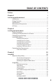
TABLE OF CONTENTS Preface i Chapter 1 1 Introducing the Motherboard 1 Introduction...........................................................................................1 Pakage Contents..................................................................................1 Specifications......................................................................................2 Motherboard Components................................................................4 I/O Ports...................................
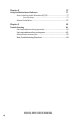
Chapter 4 77 Using the Motherboard Software 77 Auto-installing under Windows XP/7/8.......................................77 Running Setup........................................................................77 Manual Installation..........................................................................79 Chapter 5 81 Trouble Shooting 81 Start up problems during assembly..............................................81 Start up problems after prolong use............................................
Introduction Chapter 1 Chapter 1 Introducing the Motherboard Thank you for choosing the H61H2-M19 motherboard. This motherboard is a high performance, enhanced function motherboard designed to support the LGA1155 socket for latest Intel® CoreTM Family/Pentium®/Celeron® Processors*1. This motherboard is based on Intel® H61 Express Chipset for best desktop platform solution. It supports up to 16 GB of system memory with dual channel DDR3 1600*2/ 1333/1066 MHz.
Chapter 1 Specifications CPU • • • LGA1155 socket for latest Intel ® Core TM Family/Pentium ® / Celeron ® Processors Supports “Hyper-Threading” technology CPU Supports CPU up to 95W TDP Note: Please go to ECS website for the latest CPU support list. Chipset • Intel® H61 Chipset Memory • • • Dual-channel DDR3 memory architecture 2 x 240-pin DDR3 DIMM sockets support up to 16 GB Supports DDR3 1600*/1333/1066 MHz DDR3 SDRAM Note: *For Ivy Bridge CPU only.
1 1 1 1 1 2 1 2 x SPDIF out header x Front Panel audio header x LPT connector x Analog audio input connector (CD_IN) x AC power jumper x JCOM connectors (support additional eight COM ports) x SLEW header x MODE headers System BIOS • AMI BIOS with 32Mb SPI Flash ROM - Supports Plug and Play, STR (S3)/STD (S4) - Supports ACPI 2.
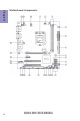
Chapter 1 4 Motherboard Components H61H2-M19 USER MANUAL
LABEL COMPONENTS LGA1155 socket for latest Intel® CoreTM Family/Pentium®/ 1. CPU Socket Celeron® Processors 2. CPU_FAN 4-pin CPU cooling fan connector 3. DDR3_1~2 240-pin DDR3 Module slots 4. SYS_FAN 3-pin system cooling fan connector 5. ATX_POWER Standard 24-pin ATX power connector 6. JCOM7-10 JCOM connector (supports additional four COM ports) 7. BZ Buzzer 8. USBPWR_F Front panel USB power select jumper 9. SATA1~4 Serial ATA 3Gb/s connectors 10. F_PANEL Front panel switch/LED header 11.
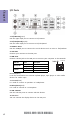
Chapter 1 I/O Ports 1. PS/2 Mouse(green) Use the upper PS/2 port to connect a PS/2 mouse. 2. PS/2 Keyboard(purple) Use the lower PS/2 port to connect a PS/2 keyboard. 3. COM1~2 Ports Use the COM1/2 port to connect the serial devices such as mice or fax/modems. 4. VGA Port Connect your monitor to the VGA port. 5. LAN Ports Connect a RJ-45 jack to the LAN port to connect your computer to the Network.
Chapter 2 Installing the Motherboard Follow these safety precautions when installing the motherboard: • • • • Wear a grounding strap attached to a grounded device to avoid damage from static electricity. Discharge static electricity by touching the metal case of a safely grounded object before working on the motherboard. Leave components in the static-proof bags.
2-3. Checking Jumper Settings This section explains how to set jumpers for correct configuration of the motherboard. Chapter 2 8 No. Components No.
1 & 2 & 4. USBPWR_F (Front panel USB power select jumper) & CLR_CMOS (Clear CMOS jumper) & USBPWR_R (Rear USB/PS2 power select jumper) Chapter 2 The following illustration shows the location of the motherboard jumpers. Pin 1 is labeled. To avoid the system instability after clearing CMOS, we recommend users to enter the main BIOS setting page to “Load Default Settings” and then “Save and Exit Setup”. 3.
5. SLEW: SLEW header Chapter 2 6.
2-4. Installing Hardware • • • • This motherboard has an LGA1155 socket. When choosing a processor, consider the performance requirements of the system. Performance is based on the processor design, the clock speed and system bus frequency of the processor, and the quantity of internal cache memory and external cache memory. You may be able to change the settings in the system Setup Utility. We strongly recommend you do not over-clock processor or other components to run faster than their rated speed.
D. Rotate the load plate onto the package IHS (Intergraded Heat Spreader). Engage the load lever while pressing down lightly onto the load plate. Secure the load lever with the hook under retention tab. Then the cover will flick automatically. Chapter 2 Please save and replace the cover onto the CPU socket if processor is removed.
• • • • • • Install the cooling fan in a well-lit work area so that you can clearly see the motherboard and processor socket. Avoid using cooling fans with sharp edges in case the fan casing and the clips cause serious damage to the motherboard or its components. To achieve better airflow rates and heat dissipation, we suggest that you use a high quality fan with 3800 rpm at least. CPU fan and heat sink installation procedures may vary with the type of CPU fan/heatsink supplied.
2-4-3. Installing Memory Modules • • Chapter 2 • • This motherboard accommodates two memory modules. It can support two 240-pin DDR3 1600*/1333/1066. Do not remove any memory module from its antistatic packaging until you are ready to install it on the motherboard. Handle the modules only by their edges. Do not touch the components or metal parts. Always wear a grounding strap when you handle the modules. You must install at least one module in any of the two slots. Total memory capacity is 16 GB.
2-4-4. Installing Add-on Cards Chapter 2 The slots on this motherboard are designed to hold expansion cards and connect them to the system bus. Expansion slots are a means of adding or enhancing the motherboard’s features and capabilities. With these efficient facilities, you can increase the motherboard’s capabilities by adding hardware that performs tasks that are not part of the basic system.
Follow these instructions to install an add-on card: Chapter 2 1 Remove a blanking plate from the system case corresponding to the slot you are going to use. 2 Install the edge connector of the add-on card into the expansion slot. Ensure that the edge connector is correctly seated in the slot. 3 Secure the metal bracket of the card to the system case with a screw. 1.
2-4-5. Connecting Optional Devices Chapter 2 Refer to the following for information on connecting the motherboard’s optional devices: No. Components No.
1 & 8. JCOM7-10/JCOM3-6: JCOM connectors (support additional eight COM ports) Chapter 2 2. SATA1~4: Serial ATA connectors SATA1~4 connectors are used to support the Serial ATA 3.0Gb/s device, simpler disk drive cabling and easier PC assembly. It eliminates limitations of the current Parallel ATA interface. But maintains register compatibility and software compatibility with Parallel ATA.
3 & 6. F_USB1~3: Front Panel USB 2.0 headers Chapter 2 The motherboard has three USB 2.0 headers supporting six USB 2.0 ports. Additionally, some computer cases have USB ports at the front of the case. If you have this kind of case, use auxiliary USB connector to connect the front-mounted ports to the motherboard. Please make sure that the USB cable has the same pin assignment as indicated above. A different pin assignment may cause damage or system hangup. 4.
5. CASE: Chassis Intrusion Detect Header This detects if the chassis cover has been removed. This function needs a chassis equipped with instrusion detection switch and needs to be enabled in BIOS. Chapter 2 7.
9. LPT: Onboard parallel port header Chapter 2 This is a header that can be used to connect to the printer, scanner or other devices. 10.
11. SPDIFO: SPDIF out header This is an optional header that provides an SPDIFO (Sony/Philips Digital Interface) output to digital multimedia device through optical fiber or coaxial connector. Chapter 2 12. F_AUDIO: Front Panel Audio Header The front panel audio header allows the user to install auxiliary front-oriented microphone and line-out ports for easier access. This header supports HD audio by default.
AC’ 97 Audio Configuration: To enable the front panel audio connector to support AC97 Audio mode. Chapter 2 If you use AC’ 97 Front Panel, please tick off the option of “ Disabled Front Panel Detect ”. If you use HD Audio Front Panel, please don’ t tick off “Disabled Front Panel Detect ” . * For reference only If you use AC’ 97 Front Panel, please don’ t tick off “Using Front Jack Detect ”. If you use HD Audio Front Panel, please tick off the option of “Using Front Jack Detect ”.
2-4-6. Installing a SATA Hard Drive This section describes how to install a SATA Hard Drive. About SATA Connectors Chapter 2 Your motherboard features four SATA connectors supporting a total of four drives. SATA refers to Serial ATA (Advanced Technology Attachment) is the standard interface for the IDE hard drives which are currently used in most PCs. These connectors are well designed and will only fit in one orientation.
2-4-7. Connecting Case Components Chapter 2 After you have installed the motherboard into a case, you can begin connecting the motherboard components. Refer to the following: No. Components No. Components 1 CPU_FAN 4 F_PANEL 2 SYS_FAN 5 ATX12V 3 ATX_POWER —— —— 1& 2. CPU_FAN (CPU cooling FAN Power Connector) & SYS_FAN (System Cooling FAN Power Connector) Connect the CPU cooling fan cable to CPU_FAN. Connect the system cooling fan connector to SYS_FAN.
3 & 5. ATX_POWER (ATX 24-pin Power Connector) & ATX12V (ATX 12V Power Connector) Connect the standard power supply connector to ATX_POWER. Connect the auxiliary case power supply connector to ATX12V. Chapter 2 Connecting 24-pin power cable The ATX 24-pin connector allows you to connect to ATX v2.x power supply. With ATX v2.x power supply, users please note that when installing 24-pin power cable, the latches of power cable and the ATX match perfectly.
4. F_PANEL: Front Panel Header Chapter 2 The front panel header (F_PANEL) provides a standard set of switch and LED headers commonly found on ATX or Micro ATX cases. Refer to the table below for information: Hard Drive Activity LED Connecting pins 1 and 3 to a front panel mounted LED provides visual indication that data is being read from or written to the hard drive. For the LED to function properly, an IDE drive should be connected to the onboard IDE interface.
Memo Chapter 2 28 H61H2-M19 USER MANUAL
Chapter 3 Using BIOS About the Setup Utility The BIOS (Basic Input and Output System) Setup Utility displays the system’s configuration status and provides you with options to set system parameters. The parameters are stored in battery-backed-up CMOS RAM that saves this information when the power is turned off. When the system is turned back on, the system is configured with the values you stored in CMOS.
Press the delete key to access BIOS Setup Utility. Aptio Setup Utility - Copyright (C) 2012 American Megatrends, Inc. Main Advanced Chipset M.I.B III Boot Security Exit Choose the system default language. BIOS Information System Language [English] System Date System Time [Wed 11/21/2012] [15:32:18] :Select Screen :Select Item Chapter 3 Enter : Select +/- : Change Opt. F1:General Help F2:Previous Values F3:Optimized Defaults F4:Save & Exit ESC:Exit Version 2.15.1229.
In this manual, default values are enclosed in parenthesis. Submenu items are denoted by a triangle . The default BIOS setting for this motherboard apply for most conditions with optimum performance. We do not suggest users change the default values in the BIOS setup and take no responsibility to any damage caused by changing the BIOS settings. BIOS Navigation Keys The BIOS navigation keys are listed below: KEY +/Enter FUNCTION Exits the current menu Scrolls through the items on a menu Change Opt.
Main Menu When you enter the BIOS Setup program, the main menu appears, giving you an overview of the basic system information. Select an item and press to display the submenu. Aptio Setup Utility - Copyright (C) 2012 American Megatrends, Inc. Main Advanced Chipset M.I.B III Boot Security Exit Choose the system default language.
Advanced Menu The Advanced menu items allow you to change the settings for the CPU and other system. Aptio Setup Utility - Copyright (C) 2012 American Megatrends, Inc. Advanced Chipset M.I.
LAN Configuration The item in the menu shows the LAN-related information that the BIOS automatically detects. Aptio Setup Utility - Copyright (C) 2012 American Megatrends, Inc. Main Advanced Chipset M.I.B III Boot Security Exit Enabled/Disabled Onboard LAN 1 Controller LAN Configuration Onboard LAN 1 Controller [Enabled] Onboard LAN 2 Controller [Enabled] :Select Screen :Select Item Chapter 3 Enter : Select +/- : Change Opt.
PC Health Status On motherboards support hardware monitoring, this item lets you monitor the parameters for critical voltages, temperatures and fan speeds. Aptio Setup Utility - Copyright (C) 2012 American Megatrends, Inc. Main Advanced Chipset M.I.B III Boot Security Exit PC Health Status Smart Fan Function : : : : : : : : -=- PECI Mode -=Offset to TCC Activation Temp. : 25O C 1896 RPM 0 RPM 1.032 V 0.468 V 1.560 V 4.980 V 12.
SMART Fan start PWM value (180) This item is used to set the start PWM value of the smart fan. SMART Fan start TEMP(-) (30) This item is used to set the start temperature of the smart fan. DeltaT (3) This item specifies the range that controls CPU temperature and keeps it from going so high or so low when smart fan works. Smart Fan Slope PWM value (10 PWM value / unite) This item is used to set the Slope Select PWM of the smart fan.
Power Management Setup This page sets up some parameters for system power management operation. Aptio Setup Utility - Copyright (C) 2012 American Megatrends, Inc. Advanced Chipset M.I.B III Boot Security Exit Power Management Setup Resume By RING Resume By PME Resume By USB 1.x/2.
ACPI Settings The item in the menu shows the highest ACPI sleep state when the system enters suspend. Main Aptio Setup Utility - Copyright (C) 2012 American Megatrends, Inc. Advanced Chipset M.I.B III Boot Security Exit ACPI Settings ACPI Sleep State [S3 (Suspend to RAM)] Select the highest ACPI sleep state the system will enter when the SUSPEND button is pressed. :Select Screen :Select Item Chapter 3 Enter : Select +/- : Change Opt.
CPU Configuration The item in the menu shows the CPU Configuration. Aptio Setup Utility - Copyright (C) 2012 American Megatrends, Inc. Advanced Chipset M.I.B III Boot Security Exit Number of cores to enable in each processor package. CPU Configuration Intel(R) Celeron(R) CPU G550T @ 2.
Excute Disable Bit (Enabled) This item allows the processor to classify areas in memory by where application code can execute and where it cannot. When a malicious worm attempts to insert code in the buffer, the processor disables code execution, preventing damage or worm propagation. Replacing older computers with Execute Disable Bit enabled systems can halt worm attacks, reducing the need for virus related repair.
SATA Configuration Use this item to show the mode of serial SATA configuration options. Aptio Setup Utility - Copyright (C) 2012 American Megatrends, Inc. Main Advanced Chipset M.I.B III Boot Security Exit SATA Mode [IDE Mode] SATA Port1 WDC WD5000AAJS (500.1GB) SATA Port2 Not Present SATA Port3 Not Present SATA Port4 Not Present :Select Screen :Select Item Enter : Select +/- : Change Opt.
USB Configuration Use this item to show the information of USB configuration. Aptio Setup Utility - Copyright (C) 2012 American Megatrends, Inc. Main Advanced Chipset M.I.B III Boot Security Exit USB Configuration USB Support Parameters All USB Devices [Enabled] Legacy USB Support [Enabled] :Select Screen :Select Item Chapter 3 Enter : Select +/- : Change Opt. F1:General Help F2:Previous Values F3:Optimized Defaults F4:Save & Exit ESC:Exit Version 2.15.1229.
Super IO Configuration Use this item to show the information of Super IO configuration. Aptio Setup Utility - Copyright (C) 2012 American Megatrends, Inc. Advanced Chipset M.I.
Serial Port 2 Configuration Scroll to this item and press to view the following screen: Main Aptio Setup Utility - Copyright (C) 2012 American Megatrends, Inc. Advanced Chipset M.I.B III Boot Security Exit Serial Port 2 Configuration Enable or Disable Serial Port (COM) Serial Port Device Settings [Enabled] IO=2F8h; IRQ=3; Change Settings [Auto] :Select Screen :Select Item Chapter 3 Enter : Select +/- : Change Opt.
Serial Port 3 Configuration Scroll to this item and press to view the following screen: Aptio Setup Utility - Copyright (C) 2012 American Megatrends, Inc. Advanced Chipset M.I.B III Boot Security Exit Serial Port 3 Configuration Enable or Disable Serial Port (COM) Serial Port Device Settings [Enabled] IO=3E8h; IRQ=6; Change Settings [Auto] :Select Screen :Select Item Enter : Select +/- : Change Opt.
Serial Port 4 Configuration Scroll to this item and press to view the following screen: Main Aptio Setup Utility - Copyright (C) 2012 American Megatrends, Inc. Advanced Chipset M.I.B III Boot Security Exit Serial Port 4 Configuration Enable or Disable Serial Port (COM) Serial Port Device Settings [Enabled] IO=2E8h; IRQ=6; Change Settings [Auto] :Select Screen :Select Item Chapter 3 Enter : Select +/- : Change Opt.
Serial Port 5 Configuration Scroll to this item and press to view the following screen: Aptio Setup Utility - Copyright (C) 2012 American Megatrends, Inc. Advanced Chipset M.I.B III Boot Security Exit Serial Port 5 Configuration Enable or Disable Serial Port (COM) Serial Port Device Settings [Enabled] IO=2F0h; IRQ=6; Change Settings [Auto] :Select Screen :Select Item Enter : Select +/- : Change Opt.
Serial Port 6 Configuration Scroll to this item and press to view the following screen: Main Aptio Setup Utility - Copyright (C) 2012 American Megatrends, Inc. Advanced Chipset M.I.B III Boot Security Exit Serial Port 6 Configuration Enable or Disable Serial Port (COM) Serial Port Device Settings [Enabled] IO=2E0h; IRQ=6; Change Settings [Auto] :Select Screen :Select Item Chapter 3 Enter : Select +/- : Change Opt.
Serial Port 7 Configuration Scroll to this item and press to view the following screen: Aptio Setup Utility - Copyright (C) 2012 American Megatrends, Inc. Advanced Chipset M.I.B III Boot Security Exit Serial Port 7 Configuration Enable or Disable Serial Port (COM) Serial Port Device Settings [Enabled] IO=240h; IRQ=11; Change Settings [Auto] :Select Screen :Select Item Enter : Select +/- : Change Opt.
Serial Port 8 Configuration Scroll to this item and press to view the following screen: Main Aptio Setup Utility - Copyright (C) 2012 American Megatrends, Inc. Advanced Chipset M.I.B III Boot Security Exit Serial Port 8 Configuration Enable or Disable Serial Port (COM) Serial Port Device Settings [Enabled] IO=248h; IRQ=11; Change Settings [Auto] :Select Screen :Select Item Chapter 3 Enter : Select +/- : Change Opt.
Serial Port 9 Configuration Scroll to this item and press to view the following screen: Aptio Setup Utility - Copyright (C) 2012 American Megatrends, Inc. Advanced Chipset M.I.B III Boot Security Exit Serial Port 9 Configuration Enable or Disable Serial Port (COM) Serial Port Device Settings [Enabled] IO=250h; IRQ=11; Change Settings [Auto] :Select Screen :Select Item Enter : Select +/- : Change Opt.
Serial Port 10 Configuration Scroll to this item and press to view the following screen: Main Aptio Setup Utility - Copyright (C) 2012 American Megatrends, Inc. Advanced Chipset M.I.B III Boot Security Exit Serial Port 10 Configuration Enable or Disable Serial Port (COM) Serial Port Device Settings [Enabled] IO=258h; IRQ=11; Change Settings [Auto] :Select Screen :Select Item Chapter 3 Enter : Select +/- : Change Opt.
Parallel Port Configuration Scroll to this item and press to view the following screen: Aptio Setup Utility - Copyright (C) 2012 American Megatrends, Inc. Advanced Chipset M.I.B III Boot Security Exit Parallel Port Configuration Enable or Disable Parallel Port (LPT/LPTE) Parallel Port Device Settings [Enabled] IO=378h; IRQ=5; Change Settings Device Mode [Auto] [Standard Parallel Port Mode] :Select Screen :Select Item Enter : Select +/- : Change Opt.
Intel(R) Smart Connect Technology Use this item to show the information of the Intel(R) Smart Connect Technology. Aptio Setup Utility - Copyright (C) 2012 American Megatrends, Inc. Main Advanced Chipset M.I.B III Boot Security Exit ISCT Configuration [Disabled] Enable/Disable ISCT Configuration :Select Screen :Select Item Chapter 3 Enter : Select +/- : Change Opt. F1:General Help F2:Previous Values F3:Optimized Defaults F4:Save & Exit ESC:Exit Version 2.15.1229.
Realtek PCIe GBE Family Controller (MAC: EC: A8: 6B: 83: 7D: B0) Use this item to show the information of the Realtek PCIe GBE Family controller. Aptio Setup Utility - Copyright (C) 2012 American Megatrends, Inc. Main Advanced Chipset M.I.B III Boot Security Exit Realtek UEFI UNDI Driver 2.017 2012/10/19 Device Information Device Name: PCI Slot: MAC Address: Realtek PCIe GBE Family Controller 04:00:00 EC: A8: 6B: 83: 7D: B0 :Select Screen :Select Item Enter : Select +/- : Change Opt.
Realtek PCIe GBE Family Controller (MAC: EC: A8: 6B: 83: 7D: B1) Use this item to show the information of the Realtek PCIe GBE Family controller. Aptio Setup Utility - Copyright (C) 2012 American Megatrends, Inc. Main Advanced Chipset M.I.B III Boot Security Exit Driver Information Driver Name: Driver Version: Driver Released Date: Realtek UEFI UNDI Driver 2.
Chipset Menu The chipset menu items allow you to change the settings for the North Bridge chipset, South Bridge chipset and other system. Main Aptio Setup Utility - Copyright (C) 2012 American Megatrends, Inc. Advanced Chipset M.I.B III Boot Security Exit System Agent (SA) Parameters System Agent Configuration PCH Configuration ME Configuration Enter : Select +/- : Change Opt. F1:General Help F2:Previous Values F3:Optimized Defaults F4:Save & Exit ESC:Exit Version 2.15.1229.
Multi-Monitor technology Multi-Monitor technology can help you to increase the area available for programs running on a single computer system through using multiple display devices. It is not only to increase larger screen viewing but aslo to improving personal productivity. Intel Integrated Graphics Chapter 3 58 PCI-Express Graphics Please note that Multi-Monitor technology supports up to four monitors: one or two Intel integrated Graphics and one or two PCI-Express graphics devices under Windows 7/8.
Chapter 3 Step 2. Install all the drivers of PCI-Express graphic cards. Click the Browse CD item, then appears the following screen. Select the driver you want to install(e.g NVIDIA GeForce 8400 GS(Microsoft Corporation-WDDM v1.1)) and double click it. Step 3. Enable IGD Multi-Monitor from BIOS. In the following BIOS screen, please set IGD Multi-Monitor to [Enabled]. Main Aptio Setup Utility - Copyright (C) 2012 American Megatrends, Inc. Advanced Chipset M.I.
Step 4. Change the appearance of your displays under Windows 7/8. 1. Enter the Control Panel menu, select the Display in the All Control Panel Items and click the Screen Resolution, then appears the following screen. Show the path of the setting location Display devices Control Panel All Control Panel Items Display Screen Resolution Search Control Panel Change the apprearance of your displays 2 3 1 Chapter 3 Display: 1.
Control Panel All Control Panel Items Display Screen Resolution Search Control Panel Change the apprearance of your displays 1 Display: 4. AL1717 Resolution: 1920 x 1200 (recommended) Orientation: Landscape Multiple displays: Disconnect this display ! Detect 4 You must select Apply before making additional changes.
PCH Configuration Scroll to this item and press to view the following screen: Main Aptio Setup Utility - Copyright (C) 2012 American Megatrends, Inc. Advanced Chipset M.I.B III Boot Security Exit Select AC power state when power is re-applied after a power failure.
ME Configuration Scroll to this item and press to view the following screen: Main Aptio Setup Utility - Copyright (C) 2012 American Megatrends, Inc. Advanced Chipset M.I.B III Boot Security Exit Management Engine Technology Configuration ME FW Version 8.1.0.1248 Enter : Select +/- : Change Opt. F1:General Help F2:Previous Values F3:Optimized Defaults F4:Save & Exit ESC:Exit Version 2.15.1229. Copyright (C) 2012 American Megatrends, Inc. ME FW Version (8.1.0.
M.I.B III (MB Intelligent BIOS III) Menu This page enables you to set the clock speed and system bus for your system. The clock speed and system bus are determined by the kind of processor you have installed in your system. Main Aptio Setup Utility - Copyright (C) 2012 American Megatrends, Inc. Advanced Chipset M.I.B III Boot Security Exit Memory Voltage Control M.I.B III (MB Intelligent BIOS III) Memory Voltage Control CPU OverClocking Configuration Chipset OverClocking Configuration Chapter 3 B.O.
CPU OverClocking Configuration Scroll to this item and press to view the following screen: Aptio Setup Utility - Copyright (C) 2012 American Megatrends, Inc. Advanced Chipset M.I.B III Boot Security Exit CPU OverClocking Configuration CPU Frequency CPU Ratio Enhanced Intel SpeedStep Technology Enhanced Intel SpeedStep Technology 100 22 [Enabled] Intel Graphics Configuration Graphics Core Ratio Limit Graphics Voltage(1/256) 20 0 :Select Screen :Select Item Enter : Select +/- : Change Opt.
Chipset OverClocking Configuration Scroll to this item and press to view the following screen: Main Aptio Setup Utility - Copyright (C) 2012 American Megatrends, Inc. Advanced Chipset M.I.B III Boot Security Exit Memory Multiplier Configuration Performance Memory Profiles [Automatic] The selection of Performance Memory Profiles which impacts memory sizing behavior.
B.O.M.P Technology (Enabled) This item allows users to enable or disable B.O.M.P technology. This function can run safe setting to setup menu when system boot fail 3 times. Auto Detect DIMM/PCI Clk (Enabled) When this item is enabled, BIOS will disable the clock signal of free DIMM/PCI slots. Spread Spectrum (Enabled) If you enable spread spetrum, it can significantly reduce the EMI (Electro-Magnetic Interference) generated by the system. Processor Speed (2200 MHz) This item shows the CPU speed.
Boot Menu This page enables you to set the keyboard NumLock state. Aptio Setup Utility - Copyright (C) 2012 American Megatrends, Inc. Main Advanced Chipset M.I.
These items will be hidden if the Fast Boot is set to be Disabled. Hard Disk Drive BBS Priorities Scroll to this item and press to view the following screen: Main Chapter 3 Network Stack Driver Support (Disabled)* If disabled, Network stack driver will be skipped. Bootup NumLock State (On) This item enables you to select NumLock state. Boot Mode select (LEGACY) Use this item to select boot mode. Set Boot Priority This item enables you to set boot priority for all boot devices.
USB Key Drive BBS Priorities Scroll to this item and press to view the following screen: Main Aptio Setup Utility - Copyright (C) 2012 American Megatrends, Inc. Advanced Chipset M.I.B III Boot Security Exit Sets the system boot order Boot Option #1 [Ut165 1.00] :Select Screen :Select Item Chapter 3 Enter : Select +/- : Change Opt. F1:General Help F2:Previous Values F3:Optimized Defaults F4:Save & Exit ESC:Exit Version 2.15.1229. Copyright (C) 2012 American Megatrends, Inc.
Security Menu This page enables you to set setup administrator password and user password. Main Aptio Setup Utility - Copyright (C) 2012 American Megatrends, Inc. Advanced Chipset M.I.B III Boot Security Exit Administrator Password Status User Password Status Not Install Not Install Set Administrator Password Administrator Password Setup Disabled Secure Boot Secure Boot Mode Image Execution Policy Key Management [Enabled] [Custom] :Select Screen :Select Item Enter : Select +/- : Change Opt.
Image Execution Policy Scroll to this item and press to view the following screen: Main Aptio Setup Utility - Copyright (C) 2012 American Megatrends, Inc. Advanced Chipset M.I.B III Boot Security Exit Internal FV Option ROM Removable Media Fixed Media [Always Execute] [Deny Execute] [Deny Execute] [Deny Execute] Image Execution Policy per device path on Security Violation.
Key Management Scroll to this item and press to view the following screen: Aptio Setup Utility - Copyright (C) 2012 American Megatrends, Inc. Advanced Chipset M.I.
Exit Menu This page enables you to exit system setup after saving or without saving the changes. Main Aptio Setup Utility - Copyright (C) 2012 American Megatrends, Inc. Advanced Chipset M.I.B III Boot Security Exit Reset the system after saving the changes.
Updating the BIOS 1 If your motherboard has a BIOS protection jumper, change the setting to allow BIOS flashing. 2 If your motherboard has an item called Firmware Write Protect in Advanced BIOS features, disable it. (Firmware Write Protect prevents BIOS from being overwritten.) 3 Prepare a bootable device or create a bootable system disk. (Refer to Windows online help for information on creating a bootable system disk.) 4 Download the Flash Utility and new BIOS file from the manufacturer’s Web site.
Memo Chapter 3 76 H61H2-M19 USER MANUAL
Chapter 4 Using the Motherboard Software Auto-installing under Windows XP/Vista/7 The auto-install DVD-ROM makes it easy for you to install the drivers and software. The support software DVD-ROM disc loads automatically under Windows XP/Vista/7. When you insert the DVD-ROM disc in the DVD-ROM drive, the auto-run feature will automatically bring up the installation screen. The screen has four buttons on it: Setup, Utilities, Browse CD and Exit. Click “Exit” button to close the Auto-Setup window.
2. Click Next. The following screen appears: Check the box next to the items you want to install. The default options are recommended. 4. Click Next to run the Installation Wizard. An item installation screen appears: 5. Follow the instructions on the screen to install the items. Chapter 4 3. Drivers and software are automatically installed in sequence. Follow the onscreen instructions, confirm commands and allow the computer to restart a few times to complete the installation.
Manual Installation Chapter 4 If the auto-install DVD-ROM does not work on your system, you can still install drivers through the file manager for your OS (for example, Windows Explorer). Look for the chipset and motherboard model, and then browse to the directory and path to begin installing the drivers. Most drivers have a setup program (SETUP.EXE) that automatically detects your operating system before installation. Other drivers have the setup program located in the operating system subfolder.
Memo Chapter 4 80 H61H2-M19 USER MANUAL
Chapter 5 Trouble Shooting Start up problems during assembly After assembling the PC for the first time you may experience some start up problems. Before calling for technical support or returning for warranty, this chapter may help to address some of the common questions using some basic troubleshooting tips. You may also log onto our ECS website for more information: http:// www.ecs.com.tw/ECSWebSite/Support/Support_FAQ.
2. From the BIOS setting, try to disable the Smartfan function to let the fan run at default speed. Doing a Load Optimised Default will also disable the Smartfan. Start up problems after prolong use After a prolong period of use your PC may experience start up problems again. This may be caused by breakdown of devices connected to the motherboard such as HDD, CPU fan, etc. The following tips may help to revive the PC or identify the cause of failure. 1. Clear the CMOS values using the CLR_CMOS jumper.
83 If fail, contact RMA CLR CMOS and restart. Yes Halt at POST screen Yes Check if monitor has display Yes Check if Power Supply Unit (PSU) is working Power Bu on is pressed but PC fails to start. - need to CLRCMOS. HDD problem.
Memo Chapter 5 84 H61H2-M19 USER MANUAL