Preface Copyright This publication, including all photographs, illustrations and software, is protected under international copyright laws, with all rights reserved. Neither this manual, nor any of the material contained herein, may be reproduced without written consent of the author. Version 1.0 Disclaimer The information in this document is subject to change without notice.
ii Declaration of Conformity This device complies with part 15 of the FCC rules. Operation is subject to the following conditions: • • This device may not cause harmful interference, and This device must accept any interference received, including interference that may cause undesired operation Canadian Department of Communications This class B digital apparatus meets all requirements of the Canadian Interferencecausing Equipment Regulations.
iii TABLE OF CONTENTS Preface i Chapter 1 1 Introducing the Motherboard 1 Introduction............................................................................................1 Feature.....................................................................................................2 Motherboard Components...................................................................4 Chapter 2 7 Installing the Motherboard 7 Safety Precautions................................................................
iv Integrated Peripherals..................................................................32 Power Management Setup.............................................................33 PCI/PnP Setup...............................................................................34 PC Health Status...........................................................................35 M.I.B. (MB Intelligent Bios)............................................................37 Load Default Settings..............................
1 Chapter 1 Introducing the Motherboard Introduction Thank you for choosing the A790GXM-AD3 motherboard. This motherboard is a high performance, enhanced function motherboard that supports socket for AMD Phenom TM II processor (socket AM3) for high-end business or personal desktop markets. The motherboard incorporates the AMD 790GX Northbridge (NB) and SB750 Southbridge (SB) chipsets. The Northbridge supports the HyperTransportTM 3.0 interface.
2 Feature Processor This motherboard uses a socket AM3 that carries the following features: • • Accommodates AMD PhenomTM II processor (socket AM3) Supports HyperTransportTM (HT) 3.0 interface speeds HyperTransportTM Technology is a point-to-point link between two devices, it enables integrated circuits to exchange information at much higher speeds than currently available interconnect technologies. This board supports CPU up to 140W TDP only.
3 Memory • • • Supports DDR3 1333/1066/800 DDR3 SDRAM with Dual-channel architecture Accommodates four unbuffered DIMMs Up to 8 GB per DIMM with maximum memory size up to 32 GB* Audio • • • • • All DACs support 192K/96K/48K/44.1KHz DAC sample rate High-quality analog differential CD input Software selectable 2.5V/3.75V VREFOUT Meets Microsoft WLP 3.08 audio requirements Direct Sound 3DTM compatible Onboard LAN • • • Supports PCI ExpressTM 1.
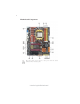
4 Motherboard Components The above image is for reference only; please take the actual motherboard for detailed parts.
5 Table of Motherboard Components LABEL COMPONENTS 1. CPU Socket 2. CPU_FAN 3. DIMM1~4 4. ATX_POWER 5. PWR_FAN 6. SYS_FAN 7. SATA1~6 8. PWR_BTN 9. PANEL 10. SPK 11. RST_BTN 12. IDE 13. F_USB1~3 14. SPDIFO 15. F_AUDIO 16. PCI1~2 17. PCIE16X_1~2 18. PCIE1~2 19. ATX4P 20. NB_FAN 21.
6 Memo Introducing the Motherboard
7 Chapter 2 Installing the Motherboard Safety Precautions • • • • • Follow these safety precautions when installing the motherboard Wear a grounding strap attached to a grounded device to avoid damage from static electricity Discharge static electricity by touching the metal case of a safely grounded object before working on the motherboard Leave components in the static-proof bags they came in Hold all circuit boards by the edges.
8 Do not over-tighten the screws as this can stress the motherboard.
9 Installing Hardware Installing the Processor Caution: When installing a CPU heatsink and cooling fan, make sure that you DO NOT scratch the motherboard or any of the surfacemount resistors with the clip of the cooling fan. If the clip of the cooling fan scrapes across the motherboard, you may cause serious damage to the motherboard or its components. On most motherboards, there are small surface-mount resistors near the processor socket, which may be damaged if the cooling fan is carelessly installed.
10 CPU Installation Procedure The following illustration shows CPU installation components. 1 2 3 4 5 Install your CPU. Pull up the lever away from the socket and lift up to 90-degree angle. Locate the CPU cut edge (the corner with the pin hold noticeably missing). Align and insert the CPU correctly. Press the lever down and apply thermal grease on top of the CPU. Put the CPU Fan down on the retention module and snap the four retention legs of the cooling fan into place.
11 Installation Procedure Refer to the following to install the memory modules. 1 2 3 4 5 6 This motherboard supports unbuffered DDR3 SDRAM only. Push the latches on each side of the DIMM slot down. Align the memory module with the slot. The DIMM slots are keyed with notches and the DIMMs are keyed with cutouts so that they can only be installed correctly. Check that the cutouts on the DIMM module edge connector match the notches in the DIMM slot.
12 Table A: DDR3 (memory module) QVL (Qualified Vendor List) The following DDR3 1333/1066/800 memory modules have been tested and qualified for use with this motherboard.
13 Expansion Slots Installing Add-on Cards The slots on this motherboard are designed to hold expansion cards and connect them to the system bus. Expansion slots are a means of adding or enhancing the motherboard’s features and capabilities. With these efficient facilities, you can increase the motherboard’s capabilities by adding hardware that performs tasks that are not part of the basic system.
14 Follow these instructions to install an add-on card: 1 2 3 Remove a blanking plate from the system case corresponding to the slot you are going to use. Install the edge connector of the add-on card into the expansion slot. Ensure that the edge connector is correctly seated in the slot. Secure the metal bracket of the card to the system case with a screw.
15 Connecting Optional Devices Refer to the following for information on connecting the motherboard’s optional devices: SATA1~6: Serial ATA connectors These connectors are used to support the new Serial ATA devices for the highest data transfer rates (3.0 Gb/s), simpler disk drive cabling and easier PC assembly. It eliminates limitations of the current Parallel ATA interface. But maintains register compatibility and software compatibility with Parallel ATA.
16 F_USB1~3: Front Panel USB headers The motherboard has six USB ports installed on the rear edge I/O port array. Additionally, some computer cases have USB ports at the front of the case. If you have this kind of case, use auxiliary USB connector to connect the front-mounted ports to the motherboard.
17 Installing a Hard Disk Drive/CD-ROM/SATA Hard Drive This section describes how to install IDE devices such as a hard disk drive and a CDROM drive. About IDE Devices Your motherboard has one IDE interface. An IDE ribbon cable supporting two IDE devices is bundled with the motherboard. You must orient the cable connector so that the pin1 (color) edge of the cable corresponds to the pin 1 of the I/O port connector.
18 Refer to the illustration below for proper installation: 1 2 3 Attach either cable end to the connector on the motherboard. Attach the other cable end to the SATA hard drive. Attach the SATA power cable to the SATA hard drive and connect the other end to the power supply. This motherboard supports the “Hot-Plug” function.
19 Connecting I/O Devices The backplane of the motherboard has the following I/O ports: PS2 Mouse Use the upper PS/2 port to connect a PS/2 pointing device. PS2 Keyboard Use the lower PS/2 port to connect a PS/2 keyboard. CLRCOMS_BTN Use the CLR_CMOS button to clear CMOS. VGA Port Connect your monitor to the VGA port. USB Ports Use the USB ports to connect USB devices. HDMI Port Connect the HDMI port to the HDMI devices.
20 Connecting Case Components After you have installed the motherboard into a case, you can begin connecting the motherboard components. Refer to the following: 1 2 3 4 5 6 7 8 9 Connect the CPU cooling fan cable to CPU_FAN. Connect the standard power supply connector to ATX_POWER. Connect the power cooling fan connector to PWR_FAN. Connect the system cooling fan connector to SYS_FAN. Connect the case switches and indicator LEDs to the PANEL. Connect the case speaker cable to SPK.
21 Connecting 8-pin power cable The ATX12V power connector is used to provide power to the CPU. When installing 8-pin power cable, the latches of power cable and the ATX12V match perfectly. 8-pin power cable CPU_FAN: Cooling FAN Power Connector Pin 1 2 3 4 Function Signal Name GND +12V System Ground Power +12V Sense Sensor PWM CPU FAN control Users please note that the fan connector supports the CPU cooling fan of 1.1A~2.2A (26.4W max.) at +12V.
22 SPK: Internal speaker Pin Signal Name 1 2 3 4 VCC Key NC Signal ATX4P: Auxiliary Power Connector for Graphics Interface Pin Signal Name 1 2 3 4 NC GND GND +12V Make sure to connect a 4-pin ATX power cable to ATX4P; otherwise, the system will be unstable.
23 Hard Drive Activity LED Connecting pins 1 and 3 to a front panel mounted LED provides visual indication that data is being read from or written to the hard drive. For the LED to function properly, an IDE drive should be connected to the onboard IDE interface. The LED will also show activity for devices connected to the SCSI (hard drive activity LED) connector.
24 Memo Installing the Motherboard
25 Chapter 3 Using BIOS About the Setup Utility The computer uses the latest “American Megatrends Inc. ” BIOS with support for Windows Plug and Play. The CMOS chip on the motherboard contains the ROM setup instructions for configuring the motherboard BIOS. The BIOS (Basic Input and Output System) Setup Utility displays the system’s configuration status and provides you with options to set system parameters.
26 Press the delete key to access the BIOS Setup Utility. CMOS Setup Utility - Copyright (C) 1985-2005, American Megatrends, Inc. Standard CMOS Setup Advanced Setup Advanced Chipset Setup Integrated Peripherals Power Management Setup PCI/PnP Setup PC Health Status M.I.B. (MB Intelligent Bios) Load Default Settings Supervisor Password User Password Save & Exit Setup Exit Without Saving : Move Enter : Select F1:General Help +/-/: Value F10: Save ESC: Exit F9: Optimized Defaults v02.
27 For the purpose of better product maintenance, the manufacture reserves the right to change the BIOS items presented in this manual. The BIOS setup screens shown in this chapter are for reference only and may differ from the actual BIOS. Please visit the manufacture’s website for updated manual. Standard CMOS Setup This option displays basic information about your system. CMOS Setup Utility - Copyright (C) 1985-2005, American Megatrends, Inc.
28 Type (Auto) Use this item to configure the type of the IDE device that you specify. If the feature is enabled, it will enhance hard disk performance by reading or writing more data during each transfer. LBA/Large Mode (Auto) Use this item to set the LBA/Large mode to enhance hard disk performance by optimizing the area the hard disk is visited each time.
29 Advanced Setup This page sets up more advanced information about your system. Handle this page with caution. Any changes can affect the operation of your computer. CMOS Setup Utility - Copyright (C) 1985-2005, American Megatrends, Inc. Advanced Setup AMD C&Q Enhanced Halt (C1E) Quick Power on Self Test Boot Up Numlock Status APIC Mode 1st Boot Device 2nd Boot Device 3rd Boot Device Hard Disk Drives Boot Other Device Enabled Disabled Enabled On Enabled Hard Drive CD/DVD Removable Dev.
30 Hard Disk Drives (Press Enter) Scroll to this item and press to view the following screen: CMOS Setup Utility - Copyright (C) 1985-2005, American Megatrends, Inc. Hard Disk Drives Hard Disk Drives 1st Drive Help Item TOSHIBA TransMemory Specifies the boot sequence from the available devices. : Move Enter : Select +/-/: Value F10: Save ESC: Exit F1:General Help F9: Optimized Defaults Press to return to the Advanced Setup page.
31 Advanced Chipset Setup This page sets up more advanced information about your system. Handle this page with caution. Any changes can affect the operation of your computer. CMOS Setup Utility - Copyright (C) 1985-2005, American Megatrends, Inc.
32 Integrated Peripherals This page sets up some parameters for peripheral devices connected to the system. CMOS Setup Utility - Copyright (C) 1985-2005, American Megatrends, Inc.
33 Power Management Setup This page sets up some parameters for system power management operation. CMOS Setup Utility - Copyright (C) 1985-2005, American Megatrends, Inc. Power Management Setup ACPI Suspend Type PWRON After PWR-Fail Resume By RING Resume By PCI/PCI-E/Lan PME Resume By USB (S3) Resume By PS2 KB (S3) Resume By PS2 MS (S3) Resume on RTC Alarm S3 Power Off Disabled Disabled Disabled Disabled Disabled Disabled Help Item Select the ACPI state used for System Suspend.
34 Resume on RTC Alarm (Disabled) The system can be turned off with a software command. If you enable this item, the system can automatically resume at a fixed time based on the system’s RTC (realtime clock). Use the items below this one to set the date and time of the wake-up alarm. You must use an ATX power supply in order to use this feature. Press to return to the main menu setting page.
35 PC Health Status On motherboards support hardware monitoring, this item lets you monitor the parameters for critical voltages, temperatures and fan speeds. CMOS Setup Utility - Copyright (C) 1985-2005, American Megatrends, Inc. PC Health Status -=- System Hardware Monitor-=Smart Fan Function Shutdown Temperature CPU Temperature System Temperature CPU Fan Speed System FAN Speed PWR Fan Speed CPU Vcore VDIMM Help Item Press Enter Disabled : 40°C/104°F : 31°C/87°F : N/A : N/A : N/A : 1.320V : 1.
36 DeltaT1 (+3) This item specifies the range that controls CPU temperature and keeps it from going so high or so low when smart fan works. SMART Fan Slope PWM value (4 PWM value/°C) This item is used to set the Slope Select PWM of the smart fan. Press to return to the PC Health Status page. Shutdown Temperature (Disabled) Enable you to set the maximum temperature the system can reach before powering down.
37 M.I.B. (MB Intelligent Bios) This page enables you to set the clock speed and system bus for your system. The clock speed and system bus are determined by the kind of processor you have installed in your system. CMOS Setup Utility - Copyright (C) 1985-2005, American Megatrends, Inc. M.I.B.
38 DRAM Timing Mode (Auto) This item enables you to specify the DRAM timing mode to be configured automatically or manually. Bank Interleaving (Auto) This item is used to set the bank interleaving. Channel Interleaving (XOR of Address bits) This item is used to set the channel interleaving. Memory CLK (400 MHz, N/A) This item is used to set the memory clock mode. CAS Latency (Tcl) (6 CLK, N/A) This item controls the timing delay (inclockcycles) before the DRAM starts a read command after receiving it.
39 Voltage Function (Disabled) Use this item to enable or disable the Voltage Function. If enable, users can increase the hardware voltage through BIOS settings. Warning: Please pay attention that doing overvoltage may result in damage to hardware. AMD Phenom (tm) II X3 720 Processor Speed (2800MHz) This is display-only field and displays the information of the CPU installed in your computer. NB Clk (2000MHz) This item shows the frequency of Northbridge clock.
40 User Password This page helps you install or change a password. CMOS Setup Utility - Copyright (C) 1985-2005, American Megatrends, Inc. User Password User Password Help Item : Not Installed Change User Password Press Enter Install or Change the password. : Move Enter : Select +/-/: Value F10: Save ESC: Exit F1:General Help F9: Optimized Defaults User Password (Not Installed) This item indicates whether a user password has been set. If the password has been installed, Installed displays.
41 Updating the BIOS You can download and install updated BIOS for this motherboard from the manufacturer’s Web site. New BIOS provides support for new peripherals, improvements in performance, or fixes for known bugs. Install new BIOS as follows: 1 If your motherboard has a BIOS protection jumper, change the setting to allow BIOS flashing. 2 If your motherboard has an item called Firmware Write Protect in Advanced BIOS features, disable it. (Firmware Write Protect prevents BIOS from being overwritten.
42 Memo Using BIOS
43 Chapter 4 Using the Motherboard Software About the Software CD-ROM The support software CD-ROM that is included in the motherboard package contains all the drivers and utility programs needed to properly run the bundled products. Below you can find a brief description of each software program, and the location for your motherboard version. More information on some programs is available in a README file, located in the same directory as the software.
44 Setup Tab Setup Click the Setup button to run the software installation program. Select from the menu which software you want to install. Browse CD The Browse CD button is the standard Windows command that allows you to open Windows Explorer and show the contents of the support CD. Before installing the software from Windows Explorer, look for a file named README.TXT, INSTALL.TXT or something similar. This file may contain important information to help you install the software correctly.
45 2. Click Next. The following screen appears: 3. Check the box next to the items you want to install. The default options are recom - 4. Click Next run the Installation Wizard. An item installation screen appears: 5. Follow the instructions on the screen to install the items. mended. 1. Drivers and software are automatically installed in sequence. Follow the onscreen instructions, confirm commands and allow the computer to restart a few times to complete the installation. 2.
46 Method 1. Run Reboot Setup Windows Vista will block startup programs by default when installing drivers after the system restart. You must select taskbar icon Run Blocked Program and run Reboot Setup to install the next driver, until you finish all drivers installation. Method 2. Disable UAC (User Account Control) * For administrator account only. Standard user account can only use Method 1.
47 2. Select Classic View. 3. Set User Account. 4. Select Turn User Account Control on or off and press Continue.
48 5. Disable User Account Control (UAC) to help protect your computer item and press OK, then press Restart Now. Then you can restart your computer and continue to install drivers without running blocked programs. Manual Installation Insert the CD in the CD-ROM drive and locate the PATH.DOC file in the root directory. This file contains the information needed to locate the drivers for your motherboard.
49 HDMI Audio setting SOP OS: XP system 1. Control Panel-->Sound and Audio Device Properties 2. a. Audio--> Sound playback--> Default device--> HD Audio Output b. Audio--> Sound playback--> Default device--> HDMI Audio Output 3. a. User Playback Audio speaker function working b.
50 OS: Vista system Control Panel--> Soundback--> Sound--> Digital Output Device (HDMI) --> Set Default 1. Volume --> Playback 2.
51 3. Speaker --> Set Default --> OK User Speaker Palyback function working 4. SPDIF-Out --> Set Default --> OK User SPDIF-Out Playback function working This concludes chapter 4.
52 Memo Using the Motherboard Software
53 Chapter 5 ATI CrossFireXTM Technology & Hybrid Graphics® Technology Support This motherboard supports ATI CrossFireXTM Technology that allows you to install multi-graphics processing units (GPU) graphics cards. Follow the installation procedures in this section. Requirements 1 2 3 4 You should have a CrossFireXTM Ready motherboard, a CrossFireXTM Edition graphics card and a CrossFireXTM ready graphics card. Visit the ECS website (www.ecs.com.
54 3. Connect the two CrossFireXTM Edition graphics cards installed on PCIE16X_1 and PCIE16X_2 slots with the CrossFire Bridge. 4. Connect the external cable to the corresponding port on your monitor. 5. Connect an auxiliary power source from the power supply to the graphics cards.
55 7. Enable the CrossFireXTM function in Catalyst Control Center. View The CatalystTM Control Center provides two views; one is Standard view for beginners, the other is Advance view for advanced users to access and configure the complete features of the software. To enable CrossFireXTM: • • • • Set the view to Advance. Click the CrossFireXTM item in Graphics Settings. In the CrossFireXTM Setting dialog, tick the box opposite Enable CrossFireXTM. Click OK to effect the setting.
56 Hybrid Graphics® Technology The Hybrid Graphics® technology provides significant display performance boost to AMD-based systems by inserting the external PCI Express graphics card and enabling both the discrete GPU and the 790GX graphics core to render simultaneously in Hybrid CrossFire® mode. Follow the steps below to start the Hybrid Graphics® technology. 1. Insert a graphics card (which can be used for Hybrid Graphics® technology, such as HD3400 series) into the PCIE16X_1 slot.
57 While if display by OnBoard, you must enter the BIOS, set the Init Display First in Advanced Chipset Setup to OnBoard. Then press F10 to save the configuration and exit the BIOS. After entering OS, enter Catalyst Control Center to enable CrossFire. 3. Click with your right mouse button on My Computer, then click the option Manage and choose the Device Manager, finally, click the Display Adapters. The following screen appears.
58 4. Enter Catalyst Control Center, you can see the option of CrossFire TM, click it and select Enable CrossFireTM, then Hybrid Graphics® starts. Note: You can only use either the CrossFireX™ technology or the Hybrid Graphics ® technology since AMD does not support the case for Hybrid Graphics ® technology by using CrossFireX™ technology and Onboard VGA. Warning: 1.
59 Chapter 6 Setting Up AMD SB750 RAID Configuration Setting Up a bootable RAID Array This section explains how to configure a bootable AMD RAID array. Setting Up the BIOS 1 Start your computer, then press Delete to enter the BIOS setup. The BIOS CMOS Setup Utility screen appears. Figure 1.1 2 BIOS CMOS Setup Utility Main Screen Use the arrow keys to select Integrated Peripherals (see Figure 1.1), then press Enter. The Integrated Peripherals screen (or a screen similar to it) appears. Figure 1.
60 4 Press F10 to save the configuration and exit. The PC reboots. 5 Enter the RAID BIOS Setup by pressing Ctrl-F when prompted, and proceed to set up the AMD RAID BIOS as described in the next section. Configuring the AMD RAID BIOS The AMD RAID BIOS set up lets you choose the RAID type and which hard drives you want to make part of the array. Entering the RAID BIOS Setup: 1 Wait until you see the RAID software prompting you to press Ctrl-F.
61 3 Select [2], then select LD 1 in the following page. The Define LD Menu screen appears (Figure 1.4). Figure 1.4 Define LD Menu Using the Define a New Array Screen If necessary, press the tab key to move from field to field until the appropriate field is highlighted. • Selecting the RAID Mode By default, this is set to Mirroring. To change to a different RAID mode, press the spacebar until the mode that you want appears in the RAID Mode box—RAID0/1/10/JBOD.
62 Assigning the Disks 1. Select the Assignment to Y to designate a free disk to be used as a RAID array disk. Figure 1.5 illustrates the Define a New Array screen after two disks have been assigned as RAID 0 array disks. Figure 1.5 FastBuild Utility—Array Disks Assigned 2. Press Ctrl-Y to save the configuration and exit. The Define LD Menu screen appears (Figure 1.6). Figure 1.
63 3. Press ESC to exit. The Main Menu screen appears (Figure 1.7). Figure 1.7 4 Main Menu Press Y to reboot. The following screen appears (Figure 1.8). Figure 1.
64 Installing the RAID Drivers Your system may come with a Windows install CD that already includes AMD RAID drivers. If so, then this section is not relevant. If that is not the case (or you are trying to install a new version of Windows), then you will need an AMD RAID driver F6 install floppy. Check to see if one came with your system. If not, you can create one by downloading the appropriate driver package and following the steps in this section. 1 Copy all files in "...
65 The following Windows Setup screen appears: Figure 1.11 Windows Setup—Selected SCSI Adapter b Select “ATI AHCI Compatible RAID Controller-x86 platform” and press Enter for 32-bit OS or Select “ATI AHCI Compatible RAID Controller-x64 platform” and press Enter for 64-bit OS. The following Windows Setup screen appears listing both drivers:. Figure 1.12 Windows Setup—AMD drives listed 5 Press Enter to continue with Windows XP Installation.
66 Memo AMD RAID Configuration