
User's Manual Part 1


2.1 System Tour
Before you start to set up system, take a moment to become familiar with the
location sand purposes of the controls, drives, connections and ports, which are
illustrated in the figures below.
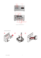
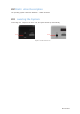
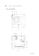
Figure 2.1 Top View
Figure 2.2 Bottom View
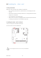
Figure 2.3 Side View
Wireless charger LED (Optional)
(Power transfer Green blink, Fault Red blink)
HDD LED
Power
Button
Wireless charger/NFC (Optional)
Speaker (Optional)
Kensington Lock
5 ECS SI mPC