
User's Manual Part 2

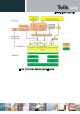
logical channels. Each logical channel corresponds to a dedicated Packet Data Network
(PDN) connection.
There is no TCP/IP stack on the modem side in the data path from IPC over PBM to
C-PS handling IP address based routing.
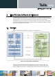
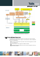
The central packet buffer manager (PBM) provides a common packet buffer used between
IPC and PS. No copy operation of data is necessary between cellular PS and IPC. The HS-
USB interface provides a highly efficient data path via DMA with scatter/gather linked-list
processing.
The control plane is using at least one dedicated channel through Serial IO component (S-IO)
to the AT command handler. The interface towards the driver is called Universal Terminal
Adapter (UTA)-Terminal, while the interface towards application is called UTA-Serial
interface. The application in our case is the AT command handler called C-AT. The control
channel is using AT commands. A detailed list of all supported AT commands can be found
in a separate application note.
In the context of an AT command based architecture, a SW multiplexer can be added. The
SW multiplexer of the 3GPP 27.010 protocol provides a number of logical channels (DLC)
which serve as AT terminals on Host PC side. These logical channels are
mapped on-top of
one of the control channels of the specific physical IPC interface.
The 3GPP 27.010 multiplexer protocol is a data link protocol (layer-2 of the OSI model)
which uses HDLC-like framing, virtual data channels, and channels’ control procedure. The
protocol is implemented according to 3GPP TS27.010. It allows software applications on the
Host processor to access the USB-HS port on M.2 in a concurrent way by emulating multiple
virtual communication channels. The MUX protocol controls the virtual channels and
conveys user data over the virtual channels.