iVMS-4000(V2.
User Manual of iVMS-4000(V2.03) Table of Contents iVMS-4000(V2.03) .................................................................................................................................................................2 User Manual............................................................................................................................................................................2 Table of Contents ..............................................................................
User Manual of iVMS-4000(V2.03) 5.6.2 Hardware Decode Mode Configuration ....................................................................................... 34 5.6.3 Hardware Decode Output Window Configuration................................................................... 35 5.6.4 Hardware Decode Preview................................................................................................................. 36 5.6.5 Secondary Output of Hardware Decode .......................................
User Manual of iVMS-4000(V2.03) 9.1.3 Network Configuration ....................................................................................................................... 79 9.1.4 Channel Configuration........................................................................................................................ 82 9.1.5 Account Management......................................................................................................................... 83 9.1.6 Others................
User Manual of iVMS-4000(V2.03) Chapter 1 Welcome to iVMS-4000 (V2.03) 1.1 Overview The iVMS-4000(V2.03) is the client application specially developed for the embedded DVR. It is applicable to DVR, hybrid DVR, NVR, DVS, IP Camera, IP Dome, decode card and accessing iVMS-2000 as well. Note: There may be technical inaccuracies, or typographical errors in the manual. The contents including description of products and program will be updated without prior notice. 1.
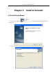
User Manual of iVMS-4000(V2.03) Chapter 2 Install & Uninstall 2.1 Install the Software Double click the program file to enter the following InstallShield Wizard as shown below: Click “Next” to enter the next step. Select “Client Software” option and then click “Next” again.
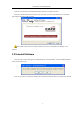
User Manual of iVMS-4000(V2.03) Input the user information and software installation location according to the hints. After that, a SADP installation wizard will pop up; click “Next” to start to install WinPcap. If it has already been installed, this step can be cancelled. Note: SADP is used as the on-line device finder; this function is unavailable if the WinPcap is not installed. 2.2 Uninstall Software Enter start menu, select “All programs””iVMS-4000(v2.
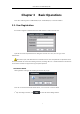
User Manual of iVMS-4000(V2.03) Chapter 3 Basic Operations Click “Start””All Programs””iVMS-4000(v2.0)”” iVMS-4000(v2.0)” to start the software. 3.1. User Registration User needs to register an administrator if the iVMS software is used for the first time. Input the user name and password in the dialog box and click “OK”. Then, user can log in as the administrator. Note: Enter, Space, and TAB buttons are invalid for the user name and password.
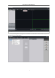
User Manual of iVMS-4000(V2.03) 2 nd step: According to the hint, right click on the default area node and then select Add Device option from the right-click menu to add a device.
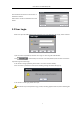
User Manual of iVMS-4000(V2.03) Enter the device information in the text box of Add Device interface. Please refer to Section 4.2 Add Device for more details. 3.2 User Login When user opens the iVMS software after registration, the login dialog box will pop up, shown as below: Input user name and password, and then click “Login” to start using the iVMS software. Click to automatically save the user name and password, then user does not need to input them again for future login.
User Manual of iVMS-4000(V2.03) 3.3 GUI Introduction The main interface of the client software is described as below: System Panel: Area Description Area Description Toolbar Menu Bar Device Area Preview Area PTZ Control Area Alarm Info Area Toolbar: Button Description Lock button. When user clicks it, the icon will change to ; re-click it to activate login window and input the correct password to unlock the interface.
User Manual of iVMS-4000(V2.
User Manual of iVMS-4000(V2.03) PTZ Control Area: Icon Options Description PTZ Control PTZ Presets Configure and call the preset Sequence Configure and call the sequence V ideo Brightness, contrast, saturation, hue and volume adjustment Alarm Info Area: Display alarm time, information and alarm sign. The area size can be enlarged by dragging the upside of the area. You can fix the area size by clicking icon “ “ ” , which will then turn to“ ”, the area size will resume to original size.
User Manual of iVMS-4000(V2.03) Chapter 4 Device Management Before any operations, user needs to add device and configure it. Click to manage the device. configure mode, and then click Area to enter the Description Area Description List area Configuration buttons Group/Shortcut key Navigation bar area 4.1 Sub-area Configuration By default, the system has the root area named as “Monitor Area”. User can right click it to add the sub-area.
User Manual of iVMS-4000(V2.03) Enter the area name and then click “OK” to save the settings. The new sub-area will be displayed under the site tree. Note: Enter, Space, TAB is invalid in the area name. It cannot be null and should not contain the following characters, including “%” and “’”. Note: When you select “Delete Node”, the sub areas, stream media servers, and devices under the root of this area will be deleted as well.
User Manual of iVMS-4000(V2.03) Port Device port (default: 8000) User Name User name of the device (default: admin) Password Password of the device (default: 12345) Channel No. The channel number of the device Multicast Used when visiting the device by the way of multicast, or else leave it blank DNS Address Used as IP address of IP server when adopting private domain, or else it can’t be filled.
User Manual of iVMS-4000(V2.03) Note: Up to 50 devices can be added. 4.3 Channel Configuration Click “Get Channel Name” to get the names of all channels. Tips: The main stream is usually used for device encoding, which sub stream is for network transmission. Double click the channel name and then the “Modify Channel Information” dialog box will pop up.
User Manual of iVMS-4000(V2.03) Series DVR is added to iVMS software, then it is accessible to add and manage the IP channels as well as to enable or disable the analog channels. Right click the device name and select “Remote Configuration”, then the “Channel Configure” menu will pop up. The “Analog Camera” will show by default. Double click the selected analog channel to enable or disable it. Note: DS-9000 series DVR can not preview and record this channel when it is disabled, unless it is enabled again.
User Manual of iVMS-4000(V2.03) Double click the selected channel to modify the parameters. Click “Delete” to delete the selected channel. After that, you can change the channel number according to the added channels. Double click the device name to modify the device information. Note: DS- 9016HFI-S DVR supports up to 16 analog channels and 8-ch IP cameras to be added. Please refer to the user manual of DS-9016HFI-S for more details.
User Manual of iVMS-4000(V2.03) 4.5 Stream Media Server Configuration When the connections is up to the limit of the device or the bandwidth is not enough, user can add the stream media server to forward real-time video stream, then it can reduce the pressure of the device network. Right click the Area node, select the “Add Stream Media Server” option, input the IP address and the Port (554 as default, need to be the same as stream media server setting), then click OK to finish. 4.
User Manual of iVMS-4000(V2.03) 4.6.2 Channel After adding the group, the channels in the site tree can be moved to the selected group. Add Channel Select the channel from the site tree, and click key to move it to the selected group. Select the device in the list area and click key and all the channels of the device can be moved to the selected group. Use and keys to adjust the channel sequence in the group list. Delete Channel Use key to delete the channel or group in the group area.
User Manual of iVMS-4000(V2.03) 4.7 Sort by Camera Configuration Click button to enter shortcut key management window. Only the channels can be added to the “Sort by camera” area. Select the channel from the list area, and click key and move it to the “Sort by camera” area. Select the device from the list area, and click key to add all the channels of the device to the sort by camera area. Use key to delete the channel in the sort by camera area.
User Manual of iVMS-4000(V2.03) Chapter 5 After configuring the device, click the Preview key to return to the preview interface. Click the “List” and “Group” keys to switch between two modes. Click key and then key and button to enter option to save current “Advanced Settings” in which user can enable the preview state including window division and preview channel for next login. The play windows are divided into 2×2 mode as default, and up to 64 window divisions can be configured.
User Manual of iVMS-4000(V2.03) Preview Panel Buttons: Area Description Area Description Play Record Capture Digital zoom Window division Full screen Page up, page down Resume cycling all the device Stop cycling all the device Show channel state Note: The window division mode and channel sequence can be remembered by the Client Software as, and will play automatically when log in next time. 5.1 Non-cycle Preview 5.1.
User Manual of iVMS-4000(V2.03) Double click the device name to preview the corresponding cameras of the device in the current window divisions. Double click the group name to preview the corresponding cameras of the group in the current window divisions. You can also preview them by dragging them to the play windows. 5.1.
User Manual of iVMS-4000(V2.03) Right click video to stop playing Right click in the play window and the menu will pop up. Click “Stop Play” and the live view will stop. Meanwhile, the play icon will change to . Stop all playing Click the key in the preview panel to stop all the live view channels. 5.2 Cycle Play 5.2.1 Cycle Configuration Click key to enter the configuration interface. Then enter the local settings interface by click “Local Settings” button.
User Manual of iVMS-4000(V2.03) 5.2.2 Cycle Play of Device/Group Start cycle Double click the device name and all the channels of the device begin to cycle in the selected window division from the 1st channel. Double click the group name and all the channels of the group begin to cycle in the selected window division from the 1st channel. Drag the node of the device to the window, and then all the channels of this device begin to cycle.
User Manual of iVMS-4000(V2.03) Click “Pause cycle” key to pause all the cycling window divisions. If the current window is in the device/group cycle mode, right click the paused window, click “Resume cycle device” to restart cycling. Click “Resume cycle devices” key to restart all the paused channels. 5.2.3 Mixed Cycle Mixed cycle mode enables iVMS software cycle previews channels of the group or sort by camera, the default window division is 2×2.
User Manual of iVMS-4000(V2.03) 5.3 Preview Control Full Screen: In preview mode, user can click key to preview in full screen. Enlarge: When in the multi-screen preview mode, double click the selected image to enlarge it, and double click again to resume. If user is previewing the zero-channel, double click it first time, it will enlarge the zero-channel, double click on window division in the zero-channel video, it will enlarge that channel to fill the zero-channel video.
User Manual of iVMS-4000(V2.03) Voice Control Right click the selected window, select “Open Voice” to enable audio preview, right click again and select “Close Voice” to disable audio preview. Note: The software only can open voice of one window at the same time. If the voice of the next window is opened then the voice of the previous will be closed automatically.
User Manual of iVMS-4000(V2.03) Channel State In preview mode, click the button to enable the display of the current channel state. And then the icon will change to , which can be selected to hide the channel state. The icons shown on the title bar are described as below: No local recording/local recording Normal signal/signal loss Normal hardware/abnormal hardware Current bitrate level (1~5) 5.
User Manual of iVMS-4000(V2.03) screen, they both max support 32 window divisions. 5.5 Recording & Capture Recording and capture is only available in the live view mode. Note: If the channel is in the recording mode, click “Stop” button to stop recording, and the preview, cycle play are stopped as well. 5.5.1 Recording Record Disk Configuration Click to enter the Local Recording Settings interface: Select the saving hard disk of recorded files in “Store setup”.
User Manual of iVMS-4000(V2.03) 5.5.2 Capture Click to enter the Local Settings interface. Image format configuration Format Selection Instruction Resolution and image quality can be changed. JPEG If capture the IP camera with higher resolution, please uncheck it. Resolution and image quality can’t be BMP changed, capture depending on current channel parameter Path configuration The default saving path is C:\Program Data\Client\Picture. User may click the button change the saving path.
User Manual of iVMS-4000(V2.03) 5.6 Hardware Decode If there is video/audio decoding card installed in the computer, then this function can be available. 5.6.1 Hardware Decode Configuration Before hardware decode on TV Wall, user needs to configure the card output and window division mode, or else it will use the default decode mode.
User Manual of iVMS-4000(V2.03) 5.6.2 Hardware Decode Mode Configuration 4000MDI decode card has two output standard: PAL & NTSC. The decode mode: ”Factory default”, ”Preview On, TV Wall On” and ”Preview Off, TV Wall On”. Consumption Mode: Enable the consumption mode to decode the video stream of 73/8100 and 90/9100 series device, if the resolution is D1, the decoding channel halve.
User Manual of iVMS-4000(V2.03) 5.6.3 Hardware Decode Output Window Configuration The “output window panel” has a multi-window division according to the total MDI card BNC number. One window is related to one BNC. Take one 4004MDI card for example, there are 4 BNCs and the “output window panel” will show you 4 windows division. The play window is named as 01-01, 02-01, 03-01 and 04-01. Select one window on “output window panel” and click the window division button to select a window division on this BNC.
User Manual of iVMS-4000(V2.03) 5.6.4 Hardware Decode Preview After configuration, click “Preview” key and select “Hardware Preview” to enter the hardware decode interface. Click meanwhile, to start decoding, and the preview windows layout will switch to the layout which is set in “output window panel”. The windows beyond the limited maximum decoding channels will not be displayed. The basic operations of hardware preview are the same with the software decode. Please refer to sections 5.1-5.
User Manual of iVMS-4000(V2.03) 5.6.5 Secondary Output of Hardware Decode The MD card can output the decoded images twice. Take 4002MD card for example, one 4002MD card can decode 4 channels CIF images, assume they are channel01, channel02, channel03, and channel04; if one decoding channel is set as 4 divisions and separately display channel01, channel02, channel03, and channel04, then the other decoding channel can only support one division and select one decoding channel to output the image.
User Manual of iVMS-4000(V2.03) 5.7 Others 5.7.1 Voice Talk & Broadcast In preview interface, right click the device name and the sub menu will pop up. Click “Start Voice Talking” to talk with the selected device. If the device is DS-9000 DVR, then there will be two voice talk channels for choice. Note: Only 1 channel of voice talk is supported by the client software at the same time. 5.7.
User Manual of iVMS-4000(V2.03) Right click area name and select “Audio Broadcast” to talk to the area. 5.7.3 Alarm Output Control Right click the device name and the sub menu will pop up. Select “Alarm Output Control” to turn on or off the alarm output, and define alarm output name. Click and it will become key, which then allows user to enable the alarm output and activate the name modified function. Re-click key to turn off the alarm output. 5.7.
User Manual of iVMS-4000(V2.03) Note: Some options will turn gray and become unavailable if the device doesn’t support the functions. 5.7.5 Remote Control Panel Right click the device name and the sub menu will pop up. Select “Remote Control Panel” and the control panel will pop up shown as figure below. You can click the buttons on the panel and control device like using front panel.
User Manual of iVMS-4000(V2.03) Chapter 6 PTZ Control 6.1 RS-485 Parameters Configuration Before PTZ operations, please make sure that RS-485 parameters has been correctly configured by iVMS software. Click “Setup” and enter the corresponding interface. Right click the device name and select “Remote Configuration” from the sub menu. Click to unfold the options, shown as figure on the right. Set right parameters of the each channel. Note: RS-485 configuration must be the same with PTZ configuration. 6.
User Manual of iVMS-4000(V2.03) window. Drag Control: There are 3×3 nine areas, when the mouse ; moves to area 1-8, the mouse icon will become as: ; ; ; ; ; ; , and continued to move the mouse along the direction shown by arrows, PTZ will move to the same directions. Note: This function is only available for software 6.3 Partial Zoom Click “Partial Zoom” to zoom in or out, the mouse icon will become as , press the left key of the mouse and drag an area you want to zoom.
User Manual of iVMS-4000(V2.03) Move the PTZ to the position you want, and click “Add” to input preset name, then click OK to finish. Then double click preset in list or click to call it. Right click preset to modify or delete this preset, 6.5 Patrol After adding two or more presets for one channel, you can set a patrol with presets for PTZ. 1st step: select one channel and click key to show patrol list.
User Manual of iVMS-4000(V2.03) 4th step: Set the time and speed for the preset. Note: The dwell time can be set between 1 and 128s; and the dwell speed is between 1 and 40. 5th step: Repeat the 2nd and 3rd step to add the presets to the patrol. Then click key to save the settings. After configuration, you can choose the patrol from the list by clicking and , and call/stop them keys. 6.6 Video Parameters Configuration Click the Move key to show the video parameters configuration menu.
User Manual of iVMS-4000(V2.03) 6.7 Keyboard and Joystick Control The iVMS client supports keyboard (DS-1002KI, DS-1003KI) and joystick control PTZ and preview window layout. Connect Ta, Tb of DS-1002KI, DS-1003KI keyboard to Rx+, Rx- of RS-485 RS-232 converter, then connect converter to COM interface of computer. Keyboard connect configuration Click , and select keyboard serial ports (None by default) in “Other Configuration”.
User Manual of iVMS-4000(V2.03) Click , and select keyboard serial ports as NULL by default to release the serial ports. 6.8 PTZ Control by Joystick Connect with a USB joystick, and a message will pop up shown as figure on the right, and define “switch button” afterwards. Press “switch button”, and a message “Controlling window layout” will pop up afterwards, and then you can move the green active box by using USB joystick.
User Manual of iVMS-4000(V2.03) Chapter 7 Recording 7.1 Local Recording 7.1.1 Store Setup Click and then to enter record setting interface It can set the record file store partition and the max record file size in the store setup. HDDs selection Choose saving hard disk of the recorded files Each disk space is less than 2G, the earliest recorded files will be overwritten to Cycle record continue recoding.
User Manual of iVMS-4000(V2.03) 7.2.1 Add NVR Server Click key to enter NVR configuration interface. Input the NVR server name, IP address and port, and click key to finish. Note: Up to 16 NVR servers can be added to the iVMS software. The default server port and VOD port are 8320 and 8554. 7.2.2 NVR Recording Mode Configuration After having finished the adding of NVR server, user can define the recording template for the schedule recording settings.
User Manual of iVMS-4000(V2.03) 1st step: Select the NVR server from the NVR drop-down menu 2nd step: Select the device or channel for recording If the device selected, it will be effective to all the channels of the device. 3rd step: Configure the recording schedule. Select the mode from “Recording plan mode” and select the disk group to save the recorded files. If required, user can also enable the stream media server and input its IP address and port in the text boxes.
User Manual of iVMS-4000(V2.03) Chapter 8 Playback Three playback modes are provided by the client software and can be selected by clicking key. Remote VOD: Searching the recorded files from hard disk of DVR or storage server. Local Playback: Searching the recorded files from hard disk of PC. Event Playback: Searching the recorded files of motion detection or alarm in signal triggered from hard disk of DVR.
User Manual of iVMS-4000(V2.03) Play Control Buttons Time Axis Area 8.1.1 Remote VOD Query 1st step: Select the window for playback and the channel from the site tree. For the channel which has been configured with NVR recording, there will be available with two options under the channel name in the site tree: Device Disk and NVR. 2nd step: Select recorded file type and query time. If user has selected NVR from the channel, then only the Schedule and Motion Detection record file types are available.
User Manual of iVMS-4000(V2.03) Select one channel then drag into playback window. If there is recorded file existed during the selected time, it will play back from the very beginning of this day. Note: 1. Up to 4 channels can be selected for synchronous playback each time. 2. When user has clicked the checkbox of Synchronous Playback to , the 4 windows will play back synchronously.
User Manual of iVMS-4000(V2.03) Note: The remote backup function is special for DS-9500 series NVR. In the single frame playback mode, every time you click button, the recorded files will play forward by one frame. Only one window audio can be opened at the same time when in VOD mode. If the audio of next window opens, then the audio of previous window will be closed. Record File Clip During playback, click once to set the start time of video clip, and click it again to set the end time of video clip.
User Manual of iVMS-4000(V2.03) In the Files Download interface, select Time Download option to enter the Time Download interface. Set the period with the start time and end time and then click the “Start download” button to download the record files and save them to your local computer. After completion of download, the system will pop up the information box indicating the record files saving path. The default saving path for the record clips and download is C: \Program Data\Client\DownLoad.
User Manual of iVMS-4000(V2.03) Digital Zoom Click can realize the digital zoom function. In the digital zoom mode, the playback window will display the video as PIP, main window display the zoom in part. Move the tape on the right, click and to change the zoom ratio. Drag the red frame, the zoom area will move with it. By rolling the mouse, user can change the zoom ratio as the same.
User Manual of iVMS-4000(V2.03) 8.2 Local Playback Click and choose “Local Playback” ( ) to enter the local playback interface. Area Description Area Description System area Device area Playback windows Query area Play control buttons Time bar area 8.2.1 Local Playback Query 1st step: Select the playback channel and window. 2nd step: Select recorded files type and query time.
User Manual of iVMS-4000(V2.03) rd 3 step: Click key to search the matched recorded files, if there are, then they will be shown in the time axis area. 4th step: Click key to start playback. You can choose time by dragging mouse to the time you want on the time axis. Select one channel and then drag it into playback window. If there is recorded file in this day, software will play back it from the very beginning of this day.
User Manual of iVMS-4000(V2.03) Button Description Button Description Open/Close sound Capture Voice control Digital zoom Pause Play Speed adjust bar Page down(for time bar Play area) Stop Single-division Play from the beginning of file 4-division Play by single frame 16-division Stop all Full Screen Note: In the single frame playback mode, every time you click button, the recorded files will play forward by one frame.
User Manual of iVMS-4000(V2.03) Area Description Area Description Device list Time line Search options Log info Note: Event playback function is supported by DS-9000/9100 series DVR, with firmware version 1.1 or higher. 8.3.1 Record Search 1st step: select a device. 2nd step: select the event type to motion detection or sensor alarm, and then select the channel/alarm input number, as well as the event date.
User Manual of iVMS-4000(V2.03) 8.3.2 Playback Control The event playback window will be shown as below: Button Description Button Description Open/close sound Video clip Pause Download record Play Single-division Stop all 4-division Capture Return to search Play Speed Adjust Bar The software only can open voice of one window at the same time. If the voice of the next window is opened then the voice of the previous will be closed automatically. 8.
User Manual of iVMS-4000(V2.03) which there is video variation, e.g., moving persons or objects, etc. User can set the start time, end time, analysis area in the video and the sensitivity. Note: Only the DS-9000/9100 DVR supports this function, and the version should be V1.2 or higher. Area Description Area Description System Area Device Area Time period Area Playback Area Dynamic analyze Area Time line Area 8.4.1 Record Search 1st step: select the channel you want to playback and analyze.
User Manual of iVMS-4000(V2.03) After having set the sensitivity, click to start drawing. Note: only after click the draw button, user could draw the analysis area. User could draw multi areas, without size and number limitation. To the same area, the higher sensitivity the more dynamic information could be detected. 8.4.
User Manual of iVMS-4000(V2.03) Button Description Button Description Open/close sound Go to next event Pause Capture Play Video Clip Stop Time axis zoom in/out Play by single frame Move the time axis Back to last event Play Speed Adjust Bar Note, under the single frame play model, it play one frame when you click button one time. Playback capture User can also get the capture by clicking button, and you will see the pop up message.
User Manual of iVMS-4000(V2.03) Chapter 9 Remote Configuration 9.1 Remote Device Configuration You can remotely configure the parameters of the device, including recording schedule, alarm schedule and etc. Click , and then click the device and select the “Remote Settings” to enter the following interface: If the device is DS-9000 series DVR, after clicking the “Remote Settings”, you need to click key in the pop-up menu to enter the configuration interface.
User Manual of iVMS-4000(V2.03) 9.1.1 Remote Recording Configuration 9.1.1.1 Encoding Parameters Configuration Select to enter encoding parameters configuration interface. Note: If the device is DS-9000 series, click “Switch to IP Channel” and select IP channel to configure the parameters of IP camera.
User Manual of iVMS-4000(V2.03) 9.1.1.2 Schedule Recording Select to enter configuration interface. Enable recording by clicking the tick . Click “Settings” of the “Record Time” to enter recording schedule configuration interface. Select “Weekday” as some day of the week or the whole week for recording time. Click for the recording type. The “All Day Recording” or 8 “Segments” can be selected as well. Note: The time of each segment can’t be overlapped.
User Manual of iVMS-4000(V2.03) 9.1.1.3 Motion Detection Recording Click to enter motion detection recording interface. Note: If the device is DS-9000 series, click “Switch to IP Channel” and select IP channel to configure the parameters of IP camera. st 1 step: Select channel number for motion detection. 2nd step: Enable motion detection to activate “Setting Area”, “Arm Schedule” and “Linkage” settings. 3rd step: Set the motion detection area and sensitivity.
User Manual of iVMS-4000(V2.03) 5th step: Set the “Trigger Recording” for linkage. Click “Setting” in the linkage area and select “Trigger Recording” tab. 6th step: Select , enable recording by clicking the tick . 7th step: Set the detection recording time. Click “Settings” of “Record Time”. Select “Weekday” as some day of the week or the whole week for recording time. for the recording type Click and change it to . The “All Day Record” or 8 “Segments” can be selected as well.
User Manual of iVMS-4000(V2.03) 9.1.1.4 Alarm Recording Select st 1 step: Select alarm input. Note: If the device is DS-9000 series DVR, you can click “Switch to IP channel” to configure the alarm input of IP channel. 2nd step: Select the type of alarm input, “NO” or “NC”. Note: The settings will become effective after rebooting. 3rd step: Enable “Alarm Handle” to activate “Arm Schedule” & “Linkage Method”.
User Manual of iVMS-4000(V2.03) 4th step: Set the arm schedule for alarm input. Click “Settings” in “Arm Schedule” menu. Select “Weekday” as some day of the week or the whole week for recording time. The “All Day Record” or 8 “Segments” can be selected as well. Note: The time of each segment can not be overlapped. th 5 step: Set recording channel triggered by alarm. Click “Settings” in “Linkage” menu and select “ Trigger Recording” tab. Enable the recording channels you want.
User Manual of iVMS-4000(V2.03) 7th step: Set the recording time for alarm input. Click “Settings” of “Record Time”. Select “Weekday” as some day of the week or the whole week for recording time. Set the record type to be . The “All Day Record” or 8 “Segments” can be selected as well. Note: The time of each segment can not be overlapped. 9.1.1.5 Other Recording Modes Other Recording Modes are including “Motion detection & Alarm”, “Motion detection | Alarm”.
User Manual of iVMS-4000(V2.03) 3rd step: Set the motion detection area and sensitivity. The sensitivity 1 and 6 are the lowest and the highest level. Enable “Start Draw”, and select the detection area by using mouse. 4th step: Set the detection time. “Arm Schedule” can be one day or the whole week, and 8 segments for one day. th 5 step: Set the alarm linkage for motion detection and select alarm output channel.
User Manual of iVMS-4000(V2.03) Upload to Center E-mail Linkage Trigger Alarm Output Upload the alarm signal to the center, such as client software When the alarm signal is detected, the client software will send the email to the designated mailbox. Trigger alarm output of the device; if the device is DS-9000 series, triggering alarm output of IP channel can be selected as well. 9.1.2.2 Signal Level Alarm Select st 1 step: Select alarm input.
User Manual of iVMS-4000(V2.03) 3rd step: Enable “Alarm Handle” to activate “Arm Schedule” & “Linkage Method”. 4th step: Set the arm schedule time for alarm input. Click “Settings” in “Arm Schedule” menu. Select “Weekday” as some day of the week or the whole week for recording time. The “All Day Record” or 8 “Segments” can be selected as well. Note: The time of each segment cannot be overlapped. 5th step: Set the alarm linkage for signal level and select alarm output channel.
User Manual of iVMS-4000(V2.03) 6th step: Set Trigger Recording for signal level alarm. 7th step: Set PTZ linkage for signal level alarm. Note: Alarm input can link PTZ of several channels, but one channel can only link one option of preset, sequence and pattern. 9.1.2.3 Video Loss If the video input signal loss, user can set relevant linkage operation. 1st step: Select the channel number for video loss.
User Manual of iVMS-4000(V2.03) 2nd step: Enable “Video Loss” to activate settings of “Arm Schedule” and “Linkage” 3rd step: Set the arm schedule for video loss. Click “Settings” in “Arm Schedule” menu. Select “Weekday” as some day of the week or the whole week for the arm schedule. The “All Day Record” or 8 “Segments” can be selected as well. Note: The time of each segment can not be overlapped. 4th step: Set linkage for video loss. Click “Settings” in the “Linkage” menu.
User Manual of iVMS-4000(V2.03) 9.1.2.4 Video Tampering 1st step: Select the channel number for video tampering. Select Note: If the device is DS-9000 series DVR, you can click “Switch to digital channel” to configure the video tampering of IP channel. 2nd step: Enable “Video Tampering Alarm” to activate settings of “Setting Areas”, “Arm schedule” and “Linkage” 3rd step: Set the video tampering area and sensitivity. The sensitivity can be divided into three levels: Low, Medium, and High.
User Manual of iVMS-4000(V2.03) 4th step: Set the arm schedule for video tampering. Click “Settings” in “Arm schedule” menu. Select “Weekday” as some day of the week or the whole week for the arm schedule. The “All Day Record” or 8 “Segments” can be selected as well. Note: The time of each segment cannot be overlapped. 5th step: Set linkage for video tampering. Click “Settings” in the “Linkage” menu. 9.1.2.
User Manual of iVMS-4000(V2.03) 9.1.3 Network Configuration 9.1.3.1 Basic Configuration Select Configure the network according to the actual situation. If there is DHCP server in the network, enable “Obtain Auto” and reboot the device to get the IP address under this network segment automatically. Select “Advance” to enter advanced configuration. You can configure preferred DNS server1 and spare DNS server2, IP address of alarm host and IP server.
User Manual of iVMS-4000(V2.03) 9.1.3.3 DDNS Adopting DDNS function can solve the problems caused by dynamic IP. Click Enable DDNS. If the “IPServerIP” is selected as protocol, then input the address where the IP server is running. If the “Dyndns” is selected as protocol: Server Name: Input the IP address of the server, such as members.dyndns.org; Domain: the domain name that user applied for the device, such as test.dynlia.
User Manual of iVMS-4000(V2.03) Select Tick to enable NTP function. Note: Time Synchronization Interval: 0~10080 min (default 60min). If the device connected to the public network, the IP address of NTP server provided by carrier can be input in the blank “Server Address”; If the device connected to private network, the IP address of NTP server built by NTP software can be input the blank “Server Address”. 9.1.3.
User Manual of iVMS-4000(V2.03) 9.1.4 Channel Configuration 9.1.4.1 Channel Display Settings Select You can configure channel name, OSD and related parameters here. 9.1.4.2 Video Mask 1st step: Select channel number, and enable video mask (i.e. ). Select Note: If the device is 9000 series, click “Switch to digital” to choose IP channel and configure the parameters.
User Manual of iVMS-4000(V2.03) 2nd step: Set the mask area. Click “Settings” to enter area set menu. Enable “Start Draw” (i.e. ), select the mask area by clicking and dragging the mouse. 9.1.4.3 Text Overlay You can add characters on the screen of the channel. Select Tick “Strings 1” (i.e. ) to enable text overlay, double click the strings area to input the characters you want to overlay on the screen. Note: If the device is DS-9000, then only analog channel support text overlay. 9.1.
User Manual of iVMS-4000(V2.03) Select Click “Add” to add user. Note: If you set the IP address or physical address, and then only the PC with the same IP address or physical address can visit the device through network. Click “Modify” to change the user name and password; click “Delete” to delete the user. Status means privilege granted, status means privilege not granted.
User Manual of iVMS-4000(V2.03) 9.1.6 Others 9.1.6.1 Remote update Click Click “Browse” to search the local upgrade file, click “Upgrade” to start upgrade remotely. 9.1.6.2 HDD Format Click Note: Please backup the data before formatting hard disk. 9.1.6.3 Zero-channel Settings Zero-channel is specially used for encoding the spot output port. User could set the spot output (zero-channel) encoding parameters, window divisions and the cycle mode.
User Manual of iVMS-4000(V2.03) Click , into the setting interface. User could enable it and then set the Bitrate, Frame rate, Split mode and the dwell time. Click , into the channel sequence settings interface, user could set the mode and the channel display sequence. 9.1.6.4 DST Settings Click the to enter the DST setting interface. Click the check box of “Enable DST”, and then set the start time and the end time of DST, and the DST bias time.
User Manual of iVMS-4000(V2.03) 9.1.6.5 Wifi Settings Click the to enter the Wifi Settings interface. User can either click the Search button to obtain the open wireless network to automatically set the Wifi parameters, or manually fill in the Wifi parameters. Click the to enter the Wlan Settings interface to set the NTC mode and other wireless parameters. 9.2 iVMS-2000 Remote Configuration User can remotely configure some parameters of the iVMS-2000 through the client software.
User Manual of iVMS-4000(V2.03) 9.2.1 General Settings Software could remotely set the general parameters of iVMS-2000. Click to set the general parameters. Click “Save” button after finish configuration. 9.2.2 Network Settings Click to set the network parameters. Click “Save” button after finish configuration.
User Manual of iVMS-4000(V2.03) 9.2.3 Camera Settings Click to set the camera parameters. Click “Save” button after finish configuration. 9.2.4 Schedule Settings Click to set record schedule.
User Manual of iVMS-4000(V2.03) 9.2.5 Alarm Settings Click to set Alarm link. 9.2.6 User Settings Click to set account information.
User Manual of iVMS-4000(V2.03) 9.2.7 E-mail Settings Click to set e-mail information. 9.3 Remote Config CCD Parameters Right click the mouse on the previewing video screen, select the “Config CCD parameters” option, open the camera CCD setting menu. note: 1, this funciton need the camera supporting. 2, different model of camera could have different parameters config interface, please refer to the actual interface.
User Manual of iVMS-4000(V2.03) White Balance Configuration Set the white balance mode. “Manual”, “Auto 1”, “Auto 2” and “Off” for your need Exposure Set the exposure time and the iris mode of the lens for your need. The exposure time need to be adjust according to the actual scene. Day/Night Mode There is “Auto”, “Day” and “Night” mode could be selected. The day-> night and night->day both have 0-7 levels to be adjusted. Number 0-7 is the threshold to fit for dark to bright scene.
User Manual of iVMS-4000(V2.03) Gamma Correction User could enable or disable the gamma correction function. If enable it, there are 0-10 levels could be adjusted. Note: this function is supported by 886, 876 IP camera only. Other For different model of IP cameras, the setting is different. On the right is for model of 886, 876. User could set the “Dead Pixel Detect”, camera HDMI local output mode, Mode trans, and other function according to different model of camera support.
User Manual of iVMS-4000(V2.03) Chapter 10 Alarm Linkage According to the various alarm signals uploaded from the device, iVMS software can configure the different linkages for them. 10.1 Linkage Configuration Click to enter the Alarm Link settings interface: 1st step: select the device from the device area on the left, activate the alarm type and alarm linkage type options.
User Manual of iVMS-4000(V2.03) 2nd step: select the alarm type, after selected, the alarm type status will become . 3rd step: select the alarm linkage type for the alarm type, and status means selected. Descriptions on Alarm Linkage Type Linkage Types Pop up image when alarm occurs Descriptions Pop up single screen image when alarm occurs.
User Manual of iVMS-4000(V2.03) If the device is on guard, right click the device name, you can select the “Cancel Guard” to cancel monitoring the alarm of the device. Right click the area name, select “Arm All” or “Disarm All” for the whole devices of the device.
User Manual of iVMS-4000(V2.03) After the device or the area fortified, the alarm linkage will become effective when there is an alarm of the device.
User Manual of iVMS-4000(V2.03) Chapter 11 E-Map Click key to show the e-map window. Toolbar Buttons Descriptions: Buttons Descriptions Buttons Descriptions Enable/Disable Map Edit Enter/Exit Full Screen Zoom Out Previous Page Zoom In Next Page Zoom Adjustment Upper Level 11.
User Manual of iVMS-4000(V2.03) 3rd step: Add the map. Click “Browse” to search the image file on the local PC. Click “OK” after renaming the file to finish. Note: Supported file formats are BMP & JPEG. 4th step: Add sub map, right click the image name in the map info area or the image itself, and the sub menu will pop up. Select “Add Sub E-map” to add sub map. Select “Properties” to change the map name and image file. 11.2 Map Configuration Map configurations need to be done under the map edit mode.
User Manual of iVMS-4000(V2.03) 2nd step: Input the name of hot spot, click and select the icon for hot spot. You can also click to change the color of characters. rd 3 step: Select the channel you want to relate to in the list “Related Camera”, and press “OK” to finish. After succeed to add hot spot, move the mouse to the icon of hot spot, it will become as , and you can move the hot spot by pressing left button and dragging.
User Manual of iVMS-4000(V2.03) Edit Hot Spot In the edit mode right click the icon of the hot spot, the edit menu will pop up. Select “Delete” to delete the hot spot; select “Properties” to change the name, appearance and related monitoring point of the hot spot. 11.2.2 Hot Region Hot region configuration can be used for displaying the sub map in the main map. Add Hot Region 1st step: Enter hot region adding interface.
User Manual of iVMS-4000(V2.03) After hot region related to the map, double click the hot region icon in the non-edit mode will show the related map. Note: You cannot edit map unless in the edit mode. Edit Hot Region In the edit mode right click the icon of the hot region, the edit menu will pop up. Select “Delete” to delete the hot region; select “Properties” to change the name, appearance and related map of the hot region.
User Manual of iVMS-4000(V2.03) Chapter 12 Utilities 12.
User Manual of iVMS-4000(V2.03) Function synchronization Remote Download Set the path for remote downloading recorded files Path Path Configuration Capture Saving The saving path of captures from preview or Path playback Configuration File The saving path for exporting the configuration file Saving Path Click “E-mail set” to open the e-mail setting interface.
User Manual of iVMS-4000(V2.03) System Log expired Time Show error message Playback on second monitor The retention period of the system log in the database Pop up the warning dialog box when error occurs Select two screen display for e-map or remote playback means start to inspect the status of the current Other Configuration devices. It will send e-mail to the appointed e-mail On-line status Inspection address when the devices are offline, go online and offline.
User Manual of iVMS-4000(V2.03) 2nd step: select type and subtype for the log you want to search for. System Log: Record information on login, logout and software configuration. Operation Log: Record information on the software operation. Alarm Log: Record information on the alarm and it needs to be linked as alarm link type. Remote Log: Record information on operations of the remote device. 3rd step: select the start time and end time for the log query, click condition will show in the list.
User Manual of iVMS-4000(V2.03) Double click the date in the list on the left, the logs of that day will show in the information list. Enable “Query by user” (i.e. ), and you can search log by users. Note: 1. The “Description” option must be supported by DS-9000/9100 series DVR with the version of 1.1.0 or higher. 2. Up to 36000 local logs or2000 remote logs can be searched and displayed.
User Manual of iVMS-4000(V2.03) Click the log with the icon in the list to play back the linked recordings. 12.2.3 Export Log Click button to export current logs as Excel or Txt format.
User Manual of iVMS-4000(V2.03) 12.
User Manual of iVMS-4000(V2.03) 12.3.1 Add & Delete User Right click the user list on the left, and select “Add User”. Input the user name, password and select the level for user, then click “OK” to finish. There are two options for user level: Administrator and Guest. Administrator has all the rights by default; as for Guest, you need to set the rights for it Double click the user name or right click it and select “Modify User” to change the password and user level.
User Manual of iVMS-4000(V2.03) Note: The administrator can be modified in the login dialog box instead of the user management. The password cannot be null and should be more than 6 characters. 12.3.2 User Rights Distribution Select a guest, and click the rights tree on the right to distribute the rights for user. Note: The operations are available for the guest only when the corresponding rights are distributed. 12.