iVMS-2000 User Manual V2.0.
I iVMS-2000 User Manual Thank you for purchasing our product. If there is any question or request, please feel free to contact us. This Manual is for iVMS-2000 Hybrid PC-DVR, iVMS-2000 PC-DVR and iVMS-2000 PC-NVR software. This manual may contain several technically incorrect places or printing errors, and the content is subject to change without notice. The updates will be added into the new version of this manual, and we will readily improve or update the product or procedure described in the manual.
II iVMS-2000 User Manual Index 1 2 Brief Introduction ............................................................................................. 1 1.1 iVMS-2000 Solution Overview .............................................................. 1 1.2 iVMS-2000 Features ............................................................................... 2 Installation and Removal ............................................................................... 4 2.1 Installation ................................
III iVMS-2000 User Manual 3.8 4 Alarm Out Manual Control ................................................................... 34 3.9 Alarm Information Bar ......................................................................... 35 3.10 Aux Preview ........................................................................................... 36 Playback ............................................................................................................. 38 4.1 Search by time ........................
IV iVMS-2000 User Manual 6.6.3 7 Remove Alarm Actions .................................................................. 94 6.7 Peripherals ............................................................................................. 95 6.7.1 SMS Configuration ......................................................................... 96 6.7.2 PTZ COM Port Configuration......................................................... 96 6.7.3 Alarm Box Configuration...............................................
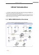
1 iVMS-2000 User Manual 1 Brief Introduction iVMS-2000 is a hybrid PCDVR software which supports full range of compression card and IP camera connection, and can be widely used in local & remote surveillance of supermarkets, stores, districts and residential places, etc. This user manual describes the function, configuration and operation steps of iVMS-2000 software.
2 iVMS-2000 User Manual 1.2 iVMS-2000 Features V2.0.2 build20100623(2010-06-23) 1. The software is divided into 3 different editions: Hybrid PC-DVR edition (32 analog video input + 32 standard/16 HD network video input), PC-DVR edition (64 analog video input) and PC-NVR edition (64 standard/32 HD network video input). 2. Support 4CIF encoding of DS-40xx-HSI series card. 3. Support remote connection via iPhone. 4. Optimized PC memory allocation and decrease memory usage consequently. 5.
3 iVMS-2000 User Manual e) Synchronized alarm information display during playback f) Support for file clip function (A-B) g) Support for snapshot acquisition during playback and in live preview h) Support for digital zoom function in playback i) Support for TV-WALL display mode j) Support of Brightness/ Contrast/ Hue/ Saturation adjusting during playback 11. E-map Functions a) Support for marking surveillance locations, alarm locations etc. b) Support for live-preview in E-Map mode.
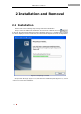
4 iVMS-2000 User Manual 2 Installation and Removal 2.1 Installation Please refer to the following steps during iVMS-2000 installation. Step1: Insert the iVMS-2000 installation CD into the PC CD-ROM, and run on the CD. The install shield dialog box will be displayed (Figure 2-1), and dialog box as Figure 2-2 will be displayed a few seconds later (the time interval depends on the PC configuration).
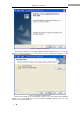
5 iVMS-2000 User Manual Figure 2-2 Welcome Interface Step3: Click “Change(C)…” to modify software installed location (Figure 2-3), and click “Next” to continue (Figure 2-4), or click “Back” to return to Welcome Interface , or click “Cancel” to exit the Installation. Figure 2-3 Select Installation Path Step4: Click “Install (I)” in the dialog box as Figure 2-4 to start iVMS-2000 installation (Figure 2-5), or click “Back (B)” to return to Select Installation Path (Figure 2-3).
6 iVMS-2000 User Manual Figure 2-4 Ready to Install Figure 2-5 Installing Step5: In Figure 2-5, a WinPcap installation wizard will pop up (software can not automatically detect and add IP cameras if WinPcap is not installed on the system), Click “Next” to start WinPcap installation (Figure 2-8). Click “Next” to continue, or click “Cancel” to cancel Installation and go to the Installation Complete Interface directly (Figure 2-12).
7 iVMS-2000 User Manual Figure 2-6 Ready to Install WinPcap If WinPcap is already installed on the PC, warning message box will prompt (Figure 2-7). Click “OK” to reinstall WinPcap, or click “Cancel” to skip WinPcap installation and go to Installation Complete Interface directly (Figure 2-12). Figure 2-7 Warning: WinPcap is already installed on the PC Step6: In Figure 2-8, click “Next” to enter the license agreement screen (Figure 2-9).
8 iVMS-2000 User Manual Figure 2-8 Welcome Interface for WinPcap Step7: In Figure 2-9, click “I Agree” to start WinPcap installation to accept the license agreement, or click “Back” to return to Figure 2-8. Click “Cancel” to skip WinPcap installation and go to Installation Complete Interface directly (Figure 2-12).
9 iVMS-2000 User Manual Figure 2-10 Installing WinPcap Step8: After W inPcap is installed, an Installation Complete Interface (Figure2-11) will pop up. Click “Finish” to complete the installation. Figure 2-11 WinPcap Installation Complete Step9: After WinPcap installation is finished, iVMS-2000 Installation Complete Inte rface will pop up (Figure 2-12), click “Finish” to complete the iVMS-2000 installation process.
10 iVMS-2000 User Manual Figure 2-12 iVMS-2000 Installation Complete Interface Note: If the version of Windows operating system is below Windows Vista, users need to install Windows updates before using CD/DVD backup function (Install the file in CD: WindowsXP-KB932716-v2-x86-ENG.exe). 2.2 Removal Please refer to the following steps before removing iVMS-2000 software from personal computers.
11 iVMS-2000 User Manual Figure 2-13 WinPcap Uninstall Interface Step2: WinPcap un-installation takes only a few seconds, after the un-installation is complete, click “Finish” in the prompt dialog box (Figure 2-14) to finish the un-Installation. Figure 2-14 WinPcap Un-installation Complete Step3: Select “All programs” →” iVMS-2000” →”Uninstall iVMS-2000” in the start menu of Windows OS, and click “Uninstall” in the prompt dialog box (Figure 2-15) to start to uninstall the iVMS-2000.
12 iVMS-2000 User Manual Figure 2-15 iVMS-2000 Un-install Prompt Step4: As shown in Figure 2-16, WinPcap un-installation process will takes a few seconds. Figure 2-16 iVMS-2000 Un-installing Step5: Uninstall completed. 2.3 Starting iVMS-2000 Double click the shortcut on system desktop, and please input default user name: admin, password: 12345 in the login dialog box (Figure 2-17).
13 iVMS-2000 User Manual Figure 2-18 Disk Management All disks with available space will be listed with available partitions. Select the partitions for recording and click “Add” button to pre -allocate space. After pre-allocation, the state of partition will change to “allocated”. Select one pre -allocated disk and click “Delete” to remove the disk from the list. Note that previously recorded files and pre -allocated space will still exist on that disk.
14 iVMS-2000 User Manual Figure 2-21 Main Interface
15 iVMS-2000 User Manual 3 Main Console 1 2 3 4 5 6 7 Figure 3-1 Main Console The following table describes the main console, in which 1, 2, 3, 7 are common to all iVMS-2000 software interfaces. Label Name Description 1 Menu Toolbar Contains System Menu, View menu, Tool Menu, Application Menu and Help Menu 2 Navigation Bar Allows the user to chose between live preview and various software configuration screens. 3 Info Display Display current time, CPU usage and network connections.
16 iVMS-2000 User Manual type. You could get more alarm information by clicking on the column. 3.1 Menu The Menu Bar is consists of System (S), View (V), Tools (T), Application (A), and Help (H) menu (Figure 3-2). Figure 3-2 Menu Bar 3.1.1 System Menu System Menu is used for logging in and out of the software as well as loading/backing -up of configuration information, etc (Figure 3-3). Figure 3-3 System Menu [Lock System] Lock current iVMS-2000 and you will not be able to carry on any operations.
17 iVMS-2000 User Manual take effect. Note: Configuration files that you want load should be located under CONFIG folder of iVMS-2000 directory. Figure 3-5 Load Configuration [Backup Configuration] Export configuration files to load later. Default name of the configuration file is current time. See Figure 3-6. Note: You can find configuration files under CONFIG folder. Figure 3-6 Backup Configuration [Default Configuration] Set configuration parameters to default value.
18 iVMS-2000 User Manual Figure 3-7 View Menu [Open All] Open all view icons on the Tab Bar below Menu Bar. [Close All] Close all view opened on Tab Bar except Main Console. [Aux Preview], [Playback], [Config], [E-Map], [TV-Wall] Click any of the items to open/close relative view page. Note: The Main Console cannot be closed and Aux Preview function will be available when you have several monitors. 3.1.3 Tool Menu Tool menu contains some tools and functions of iVMS-2000 (Figure 3-8).
19 iVMS-2000 User Manual Figure 3-9 Disk Management Note: The iVMS-2000 can’t start record until user has allocated and formatted the disk. Modification for disk partitions will take effect after restart the software. To use a partition it must have more than 2GB free space. It is recommended to use partitions in NTFS format for higher allocating speed [System Log] Query, export or delete the software operation log.
20 iVMS-2000 User Manual Figure 3-10 Log Management [Work Log] If there is some other situation in the course of operation, you can add notes here for later query. Click “Submit” button to save work log after filling in your information (Figure 3-11), and click “Search” to query work information saved previously (Figure 3-12).
21 iVMS-2000 User Manual Figure 3-12 Work Log Query [Picture Viewer] View & modify pictures captured in the process of preview or playback. (See 4.9 Picture Viewer for more) [Shortcut Key] Set shortcut key for the system in order to facilitate efficient operation of the software. Select one shortcut key and click “OK” to enable it. By default, all the shortcut keys are enabled. Preview Full Screen and Playback Full Screen are effective only in preview and playback interfaces.
22 iVMS-2000 User Manual [Connection Management] Manage network connections and set up blacklist. As shown in Figure 3-14, all current clients IP and cameras connected will be enumerated in Client IP and Connected Cameras list. Clients with IP addresses in blacklist cannot connect to the system. Figure 3-14 Connection Management [On-screen Keyboard] Open the soft keyboard which the system contains. [Windows Explorer] Open windows explorer. [Run External Program] Open another executable program.
23 iVMS-2000 User Manual 3.2 Live Preview Please make sure that you have added IP cameras or analog cameras before engaging live preview. (See 6.3.1 for more details). As shown in Figure 3-16, 8 IP cameras and 8 analog cameras are connected to the system. Figure 3-16 Camera List The following list describes the meaning of cameras and status icons: Icon Description Camera is connected and works normally. Camera is disconnected. Camera is recording. The different icons symbolize different types of record.
24 iVMS-2000 User Manual If the play area is divided into 9 parts, all 8 analog cameras will be displayed. 3.3 Live Preview in Group Mode Please make sure that you have added camera group before playing in group(See 6.4.1 Add Group for more). As shown in Figure 3-2, two groups have been added. 3.3.1 Live Preview of a Specified Group Double click on a group name in the camera list to preview the corresponding cameras of the group in the live preview area.
25 iVMS-2000 User Manual 3.4.3 Digital Zoom Click the button , a digital zoom window will pop up at lower right 1/9 size of the live preview window,as shown in Figure 3-17.The prompt window contains a red viewfinder box with buttons on the right side. The size of digital zoom viewfinder window could be adjusted by sliding mouse wheel or clicking buttons . Dragging the viewfinder and you will see zoomed image in the live preview window. Click the button again to exit digital zoom.
26 iVMS-2000 User Manual 3.4.6 Stop Live Preview Click the button to stop live preview in current window. 3.4.7 Right-Click Menu in Live Preview Mode Figure 3-19 Right-click Menu Click the right mouse button in live view window and Figure 3-19 will pop up. The following list describes the corresponding function. Name Description Set Motion Detection Set motion detection area in current live preview window, See Area 6.6.
27 iVMS-2000 User Manual 3.5.2 Full Screen Mode : Click the button to enter full screen mode, the button appears Click the button again to exit full screen mode. after clicked. 3.5.3 Stop All Cameras’ in Live Preview : Click the button to close all active windows. 3.5.4 Enable Manual Record on All Cameras : Start Manual Recording for all cameras which will not stop until the button is pressed again. The button looks like this when recording is in progress. 3.5.
28 iVMS-2000 User Manual Figure 3-20 PTZ Control Panel The meaning of icons in PTZ Control Panel is described in following list: Icon Description Directions control buttons Auto tour, looks like this when tour is active Zoom in/out Focus in/out Open/Close Iris Light, twinkling between active and when Wiper, twinkling between and when active PTZ speed control slider, l left to right slow to fast In PTZ control area, it supports some advanced operations such as setting presets, patrolling and patterns
29 iVMS-2000 User Manual Figure 3-21 Preset Operating Area (1) Add presets Click button , a prompt box for adding presets will pop up as shown in Figure 3-22, select number in the drop-down box and input preset name, click “OK” to add preset. Note: Each preset should have a unique serial number. Figure 3-22 Add Presets (2) Modify presets Click button , a prompt box for modifying presets will pop up as shown in Figure 3-23. The number of presets can not be changed or modified.
30 iVMS-2000 User Manual (4) Recall presets added Select the preset you want to recall in presets list and click button preset. You can do that by double clicking on the preset number. Note: You can also achieve preset function via right-click menu. to recall the (5) Right-click Menu Click the right mouse button in presets list and the right-click menu will pop up, as shown in Figure 3-25. In addition to above operations, the menu contains a “disable” function. You cannot recall a disabled preset.
31 iVMS-2000 User Manual Figure 3-27 Patrol Configuration Dialog (3) Remove patrol sequence Select the patrol you want to delete in patrol lis t and click the button. A confirm dialog will prompt as shown in Figure 3-28. Click “OK” to delete the patrol. Figure 3-28 Confirm Box (4) Recall patrol sequence Select the patrol in patrol list and press the button to recall it. The button appears while the patrol is active and the status bar displays “calling”. Click the button again to stop the patrol.
32 iVMS-2000 User Manual 3.6.3 Pattern Users could record the path of PTZ in patterns. Recorded patterns can be later recalled. Click button “Pattern” to enter pattern operating area. See Figure 3-30. Figure 3-30 Pattern Operating Area (1) Add pattern Click button in pattern operating area and a box will prompt as shown in Figure 3-31. Input the name and click “OK” to add a pattern. Note: Each pattern should have a unique serial number.
33 iVMS-2000 User Manual (4) Record pattern Select the pattern you want to record in and click button to start record. The button will appear and the status bar will show “Recording” in recording duration as shown in Figure 3-34. Click the button again to exit pattern recording. Figure 3-34 Record pattern (5) Recall pattern Select the pattern you have recorded and click button to call it. The button will appear and the status bar will show “Calling” in calling duration.
34 iVMS-2000 User Manual Figure 3-36 Video parameters configuration panel The following table describes meaning of icons in Figure 3-36: Icon Description Brightness. Range: 0-255,default value:128 Contrast. Range: 0-255,default value:128 Saturation. Range: 0-255,default value:128 Hue. Range: 0-255,default value:128 You can click to set video parameters default value 128. 3.8 Alarm Out Manual Control Sometimes it is necessary to manually activate alarms.
35 iVMS-2000 User Manual Figure 3-37 Alarm controlling panel Select the alarm equipment you want to trigger by checking the boxes in front. The alarm icon turns to when triggered. As shown in Figure 3-38, the network alarm (IP: 172.10.77.22, alarm out port: 5) is triggered. Uncheck the box to deactivate corresponding alarms. Figure 3-38 Two Alarm Equipments Triggered 3.9 Alarm Information Bar When the system receives an alarm message , alarm information bar will show red font blinking with an alarm bell.
36 iVMS-2000 User Manual Figure 3-39 Alarm information bar Click alarm information bar to unfold it as shown in Figure 3-40. The list enumerates alarm mode, occurrence time, alarm source a nd recording camera. You can reorder these items by clicking corresponding head column. Click to keep the information bar always visible. Click it again to hide the alarm information bar.
37 iVMS-2000 User Manual Figure 3-42 Aux preview window
38 iVMS-2000 User Manual 4 Playback Check in to enter [Playback] interface (Figure 4-1), and click again to close the [Playback] interface. 1 3 2 4 5 Figure 4-1 Playback Interface Functions of playback interface: Lab Name Description el 1 Call board Display the alarm information of the channel by play back time 2 Buttons area Search by Time, Backup, Intelligence, Clip Play, Pos Play, Alarm Log Play, Picture Viewer … 3 Video display area Display area of the record data.
39 iVMS-2000 User Manual 4.1 1 4.3 1 4.4 1 4.5 1 4.6 1 4.7 1 4.8 1 4.
40 iVMS-2000 User Manual 4.1 Search by time Click button to search record by time (Figure 4-3). 1 2 4 3 Figure 4-3 Search by time Functions of Search by time interface: Label Name Description 1 Calendar Area Display the selected date: Click the date, the data will be changed, the current date will be highlighted with a yellow square frame , and the time bar will display the recorded files for all channels on the select date, The date in the calendar which has recorded video is colored red.
41 iVMS-2000 User Manual Search single-day video data: 1. Set playback time in [Calendar Area] / [Time/Type Setting Area] 2. Set record type in [Time/Type Setting Area] (Selected all default) 3. Select channel in [Record List] 4. Click [OK] button to playback. Notes: Set the recor ding time, channel by mouse. Select an area in the [Record List] which has recorded video using a mouse, the start time of the area is the start time of the replay file.
42 iVMS-2000 User Manual 4.2 Synchronous Playback The recorded video selected in [Search by time] interface will be synchronously played in the main interface. (Figure 4-4) Figure 4-4 Synchronous Playback The playback data can be controlled by using the playback control bar at the time of playback. Playback Control Bar: Buttons in Playback Control Bar: Icon Description Press this button to hide the toolbar on the left, the playback button area and the time bar.
43 iVMS-2000 User Manual Stop Single frame play Previous Minute / Next Minute Audio Switch and Sound Control. A->B Repeat Button, during the playback process, drag the time bar to the start position you want to repeat and click A, then the button will change to B. Drag the time bar to the end position and click B. Start repeat A->B Stop repeat A->B Save A->B data 4.2.1 Playback Clips Click the [clip] button to enter the clip interface.
44 iVMS-2000 User Manual Figure 4-6 No enough space Note: The software automatically includes the clip player in the clip path in order to simplify playback. 4.2.2 Playback Window Control Bar Playback control bar is displayed at the top of the screen, Channel names displayed on the left, Video Parameter, Digital Zoom, Playback on TV-Wall, Capture, Close the playback channel on the left.
45 iVMS-2000 User Manual Figure 4-8 Video Parameter 4.2.3 Playback Time Bar The position which the yellow marker points to is the current play time. Figure 4-9 Playback Time Bar Interface Dynamically displays the time at the mouse position when the mouse enters the time bar area. All the channels will turn to the time the mouse is pointed to and start playback the if the mouse is clicked. Time adjustment of the lower right button: , : Zoom in time precision.
46 iVMS-2000 User Manual Figure 4-10 Backup Interface There will be a real-time display the size of the selected recorded file under the time bar when backing up the data. Press on the (Figure 4-11) button to preview the name and size. Figure 4-11 View Backup file Interface Backup method can select the local disk, or a CD/DVD Writer. Local Backup: 1. Select [Local Disk] radio button: 2. Click to set the local backup path. (Figure 4-12).The disk and the free space are shown in Figure 4-13.
47 iVMS-2000 User Manual Figure 4-12 Select local backup path Figure 4-13 Local backup path and free space 3. Click the backup interface. to start the backup.
48 iVMS-2000 User Manual Figure 4-14 Backup 4. Finish, pop-up the tip. (Figure 4-15) Figure4-15 Backup completed Tips Note: After clicking the button, the button will change to , click again can cancel the current backup operation. If backup is cancelled a confirmation window will be displayed.
49 iVMS-2000 User Manual 1. Select [CD/DVD Writer] radio button; 2. Select drive in the combo box and set the disk name (default is current date). (Figure 4-17) Figure 4-17 Select drive and set the disk name Note: If the CD/DVD Writer device is not connected, the [CD/DVD Writer] button will be in disabled status. (Figure 4-18) Figure 4-18 Tips: Can’t detect device. 3. Click to start burning. A progress indicator will be shown below the backup interface.
50 iVMS-2000 User Manual Note: If the version of Windows operating system is below Windows Vista, users need to install Windows updates before using CD/DVD backup function (Install the file in CD: WindowsXP-KB932716-v2-x86-ENG.exe).
51 iVMS-2000 User Manual 4.4 Intelligent Playback Intelligent Playback allows the user to search for video based on motion regions in playback. Click in the Button Area to enter the intelligent playback interface after Search by time (Figure 4-22) 6 1 2 3 4 5 Figure 4-22 Intelligent Playback Interface Steps: 1. Select channel in the [Camera] combo box (the channel being synchronizing). The channel number will be displayed in the right preview area. 2.
52 iVMS-2000 User Manual Figure 4-23 Add Region Note: Select the area which has been added and click to delete. 3. Click to quickly analyze recorded video for motion detection. The result will be added in the intelligent search result by order. (Figure 4-24) Figure 4-24 Intelligent Search Result 4. Click to stop searching. (The search will stop automatically after searching through the selected time .) 5.
53 iVMS-2000 User Manual button . 6. Click [Close] to exit intelligent playback. Notes: Intelligent playback options set Sensitivity: Sensitivity of detection to choose, 7 levels in total, 1 is the most sensitive, 7 is the most insensitive. Search Interval: The shortest time interval of the 2 motion detection. Pause when getting result: Playback will pause while search is being performed.
54 iVMS-2000 User Manual 4.5 Section Playback Section Playback: In accordance with set start and end time, average the single-channel record to 4/9/16 sections by the record time. Then playback one channel record data by the segment at the same time. Click [Section] (Figure 4-25) in the [Button Area] to enter the section playback interface. 5 1 2 3 4 Figure 4-25 Section Playback Interface Steps: 1. Select channel in the [Camera] combo box (the channel being synchronizing); 2.
55 iVMS-2000 User Manual 4.6 Clip Playback Click [Clps Play] player. (Figure 4-26) in the [Button Area] to open the clips 1 4 2 3 5 Figure 4-26 Clips Player Functions of the Clips Player: Number 1 Name Path Selected Area Description Select the path of the clip file 2 File list List all the clip files in this folder 3 Delete File Delete/Delete All 4 Screen Display Area Display area of the clip file. 5 Play Control Bar Play control operations.
56 iVMS-2000 User Manual Play button Pause button Stop button Previous frame / Next frame button. Can play the record file by frame.
57 iVMS-2000 User Manual 4.7 POS Review Pos Play: Search for POS transaction information, and playback video associated with the current POS terminal. Transaction information can be overlaid on the playback image display. (See the for details) Click [POS Play] Play interface. (Figure 4-27) in the [Button Area] to enter the POS 6 1 2 3 \ 4 \ 5 \ Figure 4-27 POS Play Interface Steps: 1. Select a POS device in the [POS Device] combo box.
58 iVMS-2000 User Manual box. Then it will only search the transactions w hich contain the keyword information. Can choose w hether to add the POS transaction information to the record video or not, through the check/uncheck radio button [Add Transaction Info]. Can pop- up a tip that displays the detailed transaction information at the mouse position w hen the mouse moves to different transaction information in the [Transaction Info] list. It is the same as the information overlaid on the recorded video.
59 iVMS-2000 User Manual 4.8 Alarm Log Review Alarm Log Play: Select channel and time, set the alarm type, look up the record video by the alarm log. Click [Alarm Log Play] alarm log play interface. in [Button Area] to enter the 6 1 2 3 \ 4 5 Figure 4-28 Alarm Log Play Interface Steps: 1. Set the start time and end time of the alarm log. 2. Set alarm type and channel which is associated with the alarm. 3. Click [Search] to start alarm log search, the result will be displayed in the [Alarm Log List].
60 iVMS-2000 User Manual 4.9 Picture View Picture Viewer: It is a tool which is used to view the captured images from live preview and playback, and edit them. Click in the [Button Area] to open the Picture Viewer or open it by clicking in the menu.
61 iVMS-2000 User Manual Icon Description Previous/Next picture Zoom in/Zoom out (do not change the original size) Clockwise/Counterclockwise Mirror/Flip Lighten/Darken, this operation is not reversible More Contrast/Less Contrast, this operation is not reversible Sharpen/Soften, this operation is not reversible Delete, delete the picture directly Print, must connect to a printer Save the modified picture as… Click the Previous/Next, Zoom in/Zoom out, or double click the picture while editing to restore t
62 iVMS-2000 User Manual 5 E-Map Click to check the [E-map] menu option in the [View] enter the E-map interface. Click again to exit. (Figure 5-1) menu bar to 2 1 3 4 5 Figure 5-1 E-Map Interface Functions of the playback interface: Number Name 1 Map Operation Bar 2 3 Map Edit Bar Tree Structure Area 4 5 Map Preview Area Eagle Eye View Area Description Switch Edit / non-editing state, cancel all the alarms Edit map and the element in the map Show all the maps and the element in the map.
63 iVMS-2000 User Manual 5.1 E-Map Operations Click [Edit] button to start edit (Figure 5-2) or exit edit (Figure 5-3). Figure 5-2Edit State Figure 5-3 Non-editing State 5.1.1 Map Operations (1)Add Map Click the [Add new map] button in the Edit State Bar to pop-up the dialog. (Figure 5-4) Input the name of the map; Click map exists. (.bmp or .jpg format); Click [OK] to add.
64 iVMS-2000 User Manual Figure 5-5 Tips: Delete map (3) Modify Map Click the [Property] button to pop-up the dialog. (Figure 5-6). Change the name of the map in the [Name] bar. Click to re-select a map; Click [OK] button to add the map or click [Cancel] to cancel the modify operation. Note: [Add sub- map] operation is the same as the [Add new map] operation. The difference is that the sub- map must be added on the map which has already been added. (Figure 5-6) Figure 5-6 Sub map 5.1.
65 iVMS-2000 User Manual Figure 5-7 Hot spot (2)Delete hot spot Select a hop spot in the Map Preview Area in edit state. Click [Delete selected] to pop-up the dialog. (Figure 5-8) Click [OK] to delete the hot spot or click [Cancel] to cancel the delete operation. Figure 5-8 Tips: Delete hot spot (3)Modify hot spot Right click on the hot spot in edit state to pop-up the right button menu . Click [Property] to pop-up the dialog Figure 5-7. Change the name of the hot spot in the [Name] bar.
66 iVMS-2000 User Manual (1)Add map link Click the [Add map link] button in edit state to pop-up the dialog. (Figure 5-9) Input the name of map link in [Name] bar. Select the associated map in [Associate] map list. Click [OK] to add map link. Figure 5-9 Map Link (1)Delete map link Select a link in Map Preview Area in edit state. Click [Delete selected] to pop-up the dialog. (Figure 5.9) Click [OK] to delete the map link or click [Cancel] to cancel delete operation.
67 iVMS-2000 User Manual Click the [Add alarm spot] button in edit state to pop-up the dialog. (Figure 5-10) Input the name of hop spot in the [Name] bar and select the associated alarm input port in [Associate] port list (See 6.7.3 Alarm box and alarm in/out configuration for detail). Click [OK] to add the alarm spot. Figure 5-10 Add alarm spot (1)Delete alarm spot Select an alarm spot in Map Preview Area in edit state. Click [Delete selected] to pop-up tips (Figure 5.9).
68 iVMS-2000 User Manual Click to move up, to move left, to move right, to move down, returns to actual size. Click or drag the slider up can zoom in the map, slider down to zoom out the map. (Figure 5-11) or drag the Figure 5-11 Map preview operation (3) Eagle Eye View Area Click to hide and to show. Drag the rectangle area in the window to partly enlarge it. The map in rectangle area is displayed in the Map Preview Area.
69 iVMS-2000 User Manual 6 Configuration Click [Config] 6-1), and click [Config] in [View] menu to enter configuration interface (Figure again to close the configuration interface. Figure 6-1 Configuration Interface Note: The configuration interface can be dragged to other VGA displays as “Aux View”.
70 iVMS-2000 User Manual 6.1 General Settings Click [General] to enter the general settings interface (Figure 6-2).
71 iVMS-2000 User Manual The General Settings mainly includes system parameters such as Log Keeping days, Snapshot Path, etc.
72 iVMS-2000 User Manual 6.2 Network Click [Network] to enter Network settings interface (Figure 6-3).
73 iVMS-2000 User Manual Network settings is for configuration of network parameters. Parameters Description Network ID Network ID to identify the software in the network, the default network ID is iVMS-2000(local host name) Network [Network] is enabled by default to allow client software and IE client connection. If [Network] is disabled, then the client software or IE client cannot connect to this iVMS-2000 server.
74 iVMS-2000 User Manual 6.3 Camera Settings Click [Camera] to enter Camera Settings interface (Figure 6-4). Users can add/delete camera inputs and modify the parameters of each camera. Figure 6-4 Camera Settings Note: · For iVMS-2000 PC-DVR edition, there is no “Add”, “Delete” and “Reboot” button. · For iVMS-2000 PC-NVR edition, there is no “Disable/Enable” button. · iVMS-2000 PC-DVR edition supports 64ch analog video input. iVMS-2000 PC-NVR edition supports 64ch standard or 32ch HD network video input.
75 iVMS-2000 User Manual Figure 6-5 Auto Detect and Add IP Cameras Notes: All the IP cameras are set with same IP address by default, and needs to be configured in [Config Parameter] (Figure 6-6). Users can select an on-line camera, input its login user name and password, and then click [Config Parameter] to modify the camera parameter as Figure 6-6. Figure 6-6 Config Parameter [Add Single IP] Select “Add Single IP” as Figure 6-7, and input the IP address, port number, user name and password.
76 iVMS-2000 User Manual Figure 6-7 Add Single IP [Add IP Range] Select “Add IP Range” as Figure 6-8, and input start/end IP address, port number, user name and password. Click [Get Camera Info] to get on-line/off-line status of this IP camera (the status will be displayed on the IP camera list). And if the camera has already been added into the system, then it will not be displayed on the list. There is a checkbox [Show online only] to enable/disable listing of off-line cameras.
77 iVMS-2000 User Manual Figure 6-9 Camera Config [Camera Name] User can select camera name by either downward list or click [Modify] button and input camera name as Figure 6-10.
78 iVMS-2000 User Manual Figure 6-11 Custom Image Quality [Network Connection Info] The camera IP, port number, login user name and password, camera number is listed here. Users can modify [Port] and [Password]. [Enable PTZ] This option should be enabled if PTZ operations are required for the camera. Click [Setup] and configure PTZ parameters as Figure 6-12. Figure 6-12 PTZ Parameters [PTZ Reverse] The PTZ operation will be reverse if this option is enabled, i.e.
79 iVMS-2000 User Manual Figure 6-13 Privacy Protect Users can set the privacy protect area via mouse dragging, and also adjust the its position and size via mouse operation. Users can also click to select a private protect area and click [Delete] to delete the privacy protect area, or click [Delete All] to delete all the privacy protect areas on the image. Note: iVMS-2000 supports up to 4 private protect areas for each camera.
80 iVMS-2000 User Manual Figure 6-14 Delete IP Cameras Note: Analog cameras cannot be deleted. 6.3.4 Reboot Cameras Select one or multiple IP Cameras on the IP Camera list, and click [Reboot] to reboot the selected IP camera(s). iVMS-2000 will automatically re-connect all the selected IP Cameras after rebooting. Note: Analog cameras cannot be rebooted. 6.3.
81 iVMS-2000 User Manual 6.4 Group Click [Group] to enter Group settings (Figure 6-15). Users can configure different camera group settings for flexible live preview configuration. Figure 6-15 Group Settings 6.4.1 Add Group Click [Add] and enter Add Group dialog box (Figure 6-16).
82 iVMS-2000 User Manual Figure 6-16 Add Group Users can modify the auto-generated group name and duration interval, and also can select between different screen split modes by clicking the appropriate icons. Click on a camera in camera list and drag it into the desired display screen position, and click [OK] to save the configuration. Users can click added camera. on the upper-right of each screen to delete the 6.4.
83 iVMS-2000 User Manual Figure 6-19 Select Camera(s) before Adding Record Schedule Select the camera in the “Modify Record Schedule” dialog box, and click [Next] to configure record schedule in the prompt dialog box (Figure 6-20): 2 1 3 4 Figure 6-20 Add Arm Schedule for Record Schedule Configuration The default record schedule is set as 24-hour arm & motion detection mode, and users can modify the schedule via configuration steps below:
84 iVMS-2000 User Manual 1. Click [Delete] / [Delete All] to delete current record schedule; 2. Click [Motion] / [Schedule] to select record mode; 3. Drag the mouse in each day’s time bar to add record schedule (support up to 8 pieces of time schedule per day), and each pieces of time schedule can be modified in position and length, users can also copy the time settings to the whole week; 4. Click [OK] to complete the record schedule settings.
85 iVMS-2000 User Manual Figure 6-22 Modify Record Schedule The modification steps are similar with operation steps in “Add Record Schedule”. 6.5.3 Remove Recording Schedules Select record schedule(s) in the schedule list and click [Delete], click [OK] in the prompt dialog box (Figure 6-23) to delete the selected record schedule(s). Figure 6-23 Delete Record Schedule 6.5.
86 iVMS-2000 User Manual Figure 6-24 Record Schedule Template There is a total of 10 record templates, of which 5 are re -configured (adjustable). Users can select the template in the drop-down list and edit its content. Click [Modify] and modify the template name, and edit record period for the template in similar way as adding record schedule.
87 iVMS-2000 User Manual 6.6 Alarm Actions Click [Alarm] and enter alarm linkage configuration interface (Figure 6-25). Users can configure link events for motion detection, video loss, video tamper and exception alarm of each camera. Figure 6-25 Alarm Linkage Configuration Interface 6.6.1 Add Alarm Actions All the motion and video tamper alarm has been automatically a dded after the camera is added into the system, and I/O alarm will also be automatically added after adding alarm box into the system.
88 iVMS-2000 User Manual Figure 6-26 Add Alarm Select the alarm input source to be added, and click [Next] to add alarm linkage (Figure 6-27, Figure 6-28 and Figure 6-29).
89 iVMS-2000 User Manual Figure 6-28 Add Camera Alarm Schedule for Alarm Linkage Figure 6-29 Add Exception Alarm Select alarm input source in [Alarm Type].
90 iVMS-2000 User Manual linkage afterwards. Note: For iVMS-2000 PC-DVR edition, there is no “Intercom exception” or “live preview exception” type. [Arm Schedule] Arm schedule for alarm linkage is set as 24-hour mode by default and the configuration steps for arm schedule is basically the same as record schedule settings. Users can set up to 8 arm periods for each day (Figure 6-30).
91 iVMS-2000 User Manual Figure 6-32 Alarm Link PTZ Configuration [Relay] Click [Enable] and set relay output for alarm linkage, there are continuous/post output modes for relay configuration (Figure 6-33). Figure 6-33 Relay Settings for Alarm Linkage [Others] Click [Prompt E-map], [Send SMS], [Upload Alarm], [Sound Alarm], [Send Email] or [Prompt Video] to configure other alarm linkage settings.
92 iVMS-2000 User Manual Figure 6-34 Other Alarm Linkage Configuration Select [Sound Alarm] and select .wav files in the drop-down list. Please refer to the [Sound Config] of [Other] Configuration interface. Select [Send Email] and select snapshot camera (or disable alarm snapshot). Please refer to the [Email Config] of [Other] Configuration interface. Select [Prompt video] and select the camera live preview video to be prompt on alarm. Users can select up to 4 cameras (Figure 6-35).
93 iVMS-2000 User Manual Figure 6-36 Copy Video Loss Linkage Configuration 6.6.2 Modify Alarm Actions Select an alarm input and modify the alarm input configuration; or select an alarm input under a certain camera and modify all the alarm configuration for each camera; or select an exception alarm type and modify all the alarm types. Alarm linkage modification steps are generally the same as add alarm linkage, except for the region settings under motion detection/ video loss link configuration.
94 iVMS-2000 User Manual Figure 6-38 Set Video Tamper Area Click [Region] during video tamper alarm modification and enter “Set Video Tamper Area” dialog box. The operation steps for Add/Modify/Move/Delete areas are similar to motion detection area configuration, and users can adjust the sensitivity level and click [Start Test]. If there is video tamper detected in the region, the brims of the blocks in the motion detection areas will flicker in red/green/blue colors.
95 iVMS-2000 User Manual 6.7 Peripherals Click [Peripheral] and enter peripheral configuration interface (Figure 6-40), and configure peripheral devices like serial port, alarm box, etc. Figure 6-40 Peripherals Configuration Interface Note: · For iVMS-2000 PC-DVR edition, there is no “Add Network Alarm” button. · For iVMS-2000 PC-NVR edition, there is no serial port configuration option for “Local PTZ”.
96 iVMS-2000 User Manual 6.7.1 SMS Configuration Users can configure COM port and mobile phone number to receive the short message in the SMS configuration interface, and the SMS configuration is related to the SMS alarm linkage configuration. A GSM/GPRS modem is required for SMS function (Please refer to the installation guide of GSM/GPRS Modem for its configuration steps).
97 iVMS-2000 User Manual Figure 6-41 Add Alarm Box Notes: The COM port for alarm box cannot be duplicated with COM port for SMS or PTZ. [Add Network Alarm] Add sensor input and relay output for IP Cameras (Figure 6-42). Select the sensor or relay and click [OK] to add. Users can also test sensor or relay as when adding alarm box.
98 iVMS-2000 User Manual Figure 6-42 Add Network Alarm [Modify] Select any of the network sensor and then modify all the network sensor configuration, or select any of the network relay and then modify all the network relay configuration, or select any of the alarm box and then modify all the alarm box configuration. [Delete] Select the sensor(s), relay(s) or alarm box(es) and click [Delete] to delete the alarm settings.
99 iVMS-2000 User Manual 6.8 Configuration of User Accounts Click [User] and enter user configuration interface (Figure 6-43), and add, delete or modify user account and privileges. Figure 6-43 User Configuration Interface There is a default administrator account for the system: admin, with its password: 12345. Only this user has complete privilege and is able to add, delete or modify other user accounts, while all the other users can only modify their own passwords.
100 iVMS-2000 User Manual Notes: Users can modify the password directly via “Modify Password” under system menu. [Delete] Select an operator account on the user list and click [Delete], and then click [OK] in the prompt dialog box to delete this user (Figure 6-45) Figure 6-45 Delete User Notes: Only admin has the privilege to delete the operator accounts, and the admin account cannot be deleted.
101 iVMS-2000 User Manual 6.9 Others Click [Others] to enter other configuration interface (Figure 6-46). This configuration interface is mainly used for email and alarm audio settings, etc. Users can click the Tabs above to switch between different setting pages . Figure 6-46 Other Configuration Interface [Alarm Audio] Audio files for alarm linkage configuration. There are 4 default alarm audio files in the iVMS-2000 system, and the users can add no more than 12 audio files (Figure 6-47).
102 iVMS-2000 User Manual Figure 6-48 Add Audio File [Modify] Modify the audio file and name (Figure 6-49). Figure 6-49 Modify Audio File [Delete] Select an audio file in the audio file list (the 4 default files cannot be deleted), click [Delete] and then click [OK] on the prompt dialog box (Figure 6-50). Figure 6-50 Delete Audio File Notes: the 4 default audio files cannot be deleted. [Email] ConFigure send/ receive address and content, etc for alarm linked email configuration (Figure 6-51).
103 iVMS-2000 User Manual Figure 6-51 Email Configuration Users need an mail account which supports SMTP to send the email. Click [SMTP Settings] and set the Email account for the sender (Figure 6-52). Figure 6-52 SMTP Settings After SMTP settings are properly configured, users can click [Test] and test if this account can send the emails correctly. The SMTP account will send a test email to its own address then, and if the users receive the test email properly, please follow the operation steps below.
104 iVMS-2000 User Manual 7 Appendix 7.1 Devices Supported by iVMS-2000 iVMS-2000 Edition Hybrid PC-DVR (32ch analog video input + 32ch standa rd /16ch HD network video input) PC-NVR (64ch standa rd /32ch HD network video input) PC-DVR (64ch analog video input) Devices Supported by iVMS-2000 Device Type Product Series Network Ca mera & Network Speed Dome 2Mega Pi xel Network Ca mera /Speed Dome & all the other series below this resolution DVS DS-60xx & DS-61xx series HIK H.
105 iVMS-2000 User Manual 7.
106 iVMS-2000 User Manual Baud Rate Baud rate is the number of bits transmitted per second, i.e. 300 bit/s stands for 300 bits are sent per second; and if the PTZ protocol needs 4800 as baud rate, then it represents the clock cycle is 4800Hz, and the serial port communication sampling rate is also 48000HZ.
107 iVMS-2000 User Manual The whole monitoring image is divided into various small areas, among which users can select any areas with different sensitivity level, and the movements in these areas will be detected by the camera and trigger motion record. Video Tamper Alarm Alarm when video being tampered Privacy Mask Mask certain area of the image.
108 iVMS-2000 User Manual representation of horizontal and vertical pixels. Image resolution refers to the size of digital image, also represented by horizontal and vertical pixels. If the image resolution is bigger than display resolution, then some images can’t be displayed. Pixel resolution refers to a ratio of pixel’s width and length. Different ratio will cause the deformation of images.