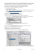
This section contains an example of configuring Sony Ipela Embedded Analytics. When configuring the embedded analytics of other devices, you should use their descriptions in the interface of the software package or, for more detail, the official reference documentation for these devices. Procedure for Configuring Sony Ipela Embedded Analytics You can configure Sony Ipela embedded analytics as follows: 1. Create a detection tool object. 2. Set the detection tool parameters. 3.
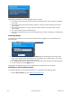
3. If you selected motion detection (Motion in the Detect list), set the following parameters ( 2): a. To enable the mode in which the detection tool also responds to stopping, select Yes i n the Respond to stopping list. b. In the Rest time field, indicate in seconds the rest time of an object after which the motion detection tool registers stopping (if you executed step 3.1). This value should be in the range [2, 60]. c.
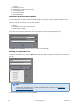
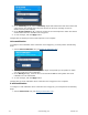
Perform the follow actions for the Sensor detection tool, on the Detection Tools tab: 1. Check triggering of the detection tool with the help of the Triggers ribbon (optional) (see the section Checking the Triggering of a Detection Tool. 2. Set the rules to be automatically executed when the detection tool is triggered (see the section titled Configuring Automatic Rules). Checking the Triggering of a Detection Tool You can check the triggering of detection tools in the Detection Tools tab.
Checking the triggering of a detection tool is now complete. Configuring Automatic Rules Automatic rules are particular actions that are performed when a detection tool is triggered. One or multiple automatic rules can be set for each detection tool. The interface for configuring automatic rules is shown when any detection tool is selected: Types of Automatic Rules When a detection tool is triggered, one or more rules may be executed: 1. Recording to the archive and initiation of an alarm in the system.
3. 4. 5. 6. 7. camera. Switching a relay. Switching to a PTZ camera preset. Sound notification. E-mail notification. SMS notification. Automatic Rule Execution Modes You can select the execution mode of all automatic rules set for a video camera's detection tool. The rules can be executed in one of three modes: 1. Always. 2. Processing only in the armed mode. 3. Within time schedule. The mode for performing automatic rules is selected from the corresponding list (1).
To save the automatic rule, click the Apply button. To add other automatic rules, repeat the original procedure. Note To delete an automatic rule, click the save changes button and click the Apply button to Conditions for Setting Automatic Rules Before setting automatic rules to be executed when a detection tool is triggered, you must make sure that the following objects have been created and configured.
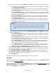
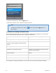
Recording to Archive and Initiation of an Alarm To configure recording to the archive and the initiation of an alarm when a detection tool is triggered, you must perform the following steps: 1. Add the Record to archive rule (see Adding an automatic rule). 2. In the Alarm list (1), select the mode for initiating a system alarm. 3. In the Camera list (2), select the video camera for which the rule will be performed. 4.
flag will be shifted back from the actual time the alarm was triggered. Note If the alarm flag position is set, playback of an event received for processing begins from the moment corresponding to the flag's position, and not from the moment of the beginning of the alarm b. In the Post-record time field (2), enter the post record time, which is the length in seconds of post-alarm recording which will be added to the end of the recording made in connection with the alarm.
The following procedure is used for displaying video cameras: 1. The system searches for layouts that contain the specified video camera and are accessible to the user. 2. The system chooses the layout with the minimum number of cells to display the selected video camera. 3. If the required layout does not yet exist, the system creates a new layout with a single video camera. 4. The system switches to the selected layout. 5.
2. In the Telemetry list (1) select a Telemetry object that matches the PTZ device of the PTZ video camera. The pan/tilt unit of any PTZ camera can be used, including one tied to another server (if it is enabled). 3. In the Preset number list (2), select the number of the camera preset to which the camera should switch when the detection tool is triggered. 4. To save changes, click the Apply button. Configuration of switching to a PTZ camera preset is now complete.
2. In the Select e-mail list (1), select the e-mail object which will be used for e-mail notification when a detection tool is triggered. 3. In the Message subject field of the window which appears (2), enter the subject of the e-mail message which will be sent when the detection tool is triggered. 4. In the E-mail text field (3), enter the text which should be sent in an e-mail message when the detection tool is triggered. 5. To save changes, click the Apply button.
On the base of one server you can create an unlimited number of archives. An archive can be distributed on several volumes of the server. On one volume for one archive you can create only one partition, which occupies either a file of a set size or the entire volume. Procedure for Configuring Archives You can configure archives as follows: 1. Create archives with the desired parameters. 2. Configure recording of the video stream from video cameras to the archive.
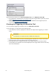
3. In the Basic properties group (2), identify the archive: a. in the Archive name field, enter the desired archive name. b. From the Color list, select a color to label the archive. 4. Place the archive partitions on one or several volumes of the server 3): a. From the Partition type list, select the desired type of archive partition on the disk: a file or the entire volume. Note The system disk cannot be completely allocated for an archive b. If you select a File partition, enter the full path to the .
Note The size of an archive partition on a disk should be greater than 1 GB Note If you are creating an archive based on an existing file, the Archive size field automatically displays the size of the file. It may be changed d. If the Disk partition is chosen, you must manually delete the file system on the selected disk by using the Windows disk management utility and then repeat the archive creation procedure. To start this utility, click the Disk operations button.
7. Read through the list of partitions that will be formatted. If the list is correct, select I have read the warning and realize the risk of losing important data, then click Format. Otherwise, click Cancel to return to the archive settings. Creation of an archive with the desired parameters is now complete. The archive size relative to the total amount of space on system disks is displayed in the Allocati on of archives chart.
2. In the Mode list (3), select the desired mode of recording the video stream from the video camera to the archive.
Note Pre-alarm recording is the period of pre-event recording that will be added to the beginning of an alarm event recording 8. Repeat steps 1–6 to configure recording of the video stream from a camera to all desired archives. 9. Click the Apply button. Configuration of recording of the video stream from a camera to archives is complete. Note The archive's icon in the linked archive(s)table automatically changes based on the recording settings.
Note The value of the predicted archive capacityis constantly calculated and recalculated. The longer you have been recording to the archive, the more precise this estimate will be. To refresh the predicted archive capacity, re-select the archive in the list Deleting Archives You can delete an archive from the system. Attention! When an archive is deleted, the archive file or partition is not physically removed.
After you configure a user's layouts, you may want to limit that user's privileges. Layouts ribbon modes EyStream has two types of layouts: standard and custom (see Switching between layout types). The standard layouts are an automatically defined set of layouts. Standard layouts cannot be created, deleted, or edited. Each button on the layouts ribbon represents a group of layouts of the same type. The layouts in a group differ only in the video cameras contained within them.
2. Select the layout type in the corresponding drop-down list (3). 3. Click the Apply button to save the settings. The layout ribbon will then operate in the selected mode. Note Switching layout modes is allowed only for users with Layout configuration per missions Creating and deleting layouts Layouts are created based on standard layout types. To create a new layout, select one of the standard layouts in the context menu of the layouts ribbon. The newly created layout will be named automatically.
Select the layout that you want to copy. Click the Duplicate layout. button to open the context menu and select An identical layout is then created. Note Layouts cannot be copied while in editing mode Editing layouts Switching to layout editing mode To edit layouts, go to the Layouts tab. To switch to editing mode, click the the context menu of the layouts ribbon. Select Edit layout. button to open In layout editing mode, space is divided by a grid of equal-sized squares for holding viewing tiles ( 1).
On the edge of the layout there are grid square fragments (2), which are parts of ordinary empty cells and allow adding new cells to the layout (see XXX). Actions available during layout editing The following actions are available in layout editing mode: 1. 2. 3. 4. 5. 6. Select a layout for editing. Add new viewing tiles to a layout. Change the sizes of viewing tiles. Move viewing tiles. Select a video camera in a viewing tile. Select video stream quality in a viewing tile. 7.
Adding new viewing tiles to a layout You can add new viewing tiles to a layout in one of three ways: 1. Left-click a grid square fragment and drag the viewing tile to the grid square, or drag the square to any of the layout windows (see Moving viewing tiles). 2. Left-click a grid square fragment and resize it (see Resizing a viewing tile). 3. Left-click a grid square fragment and select a video camera in it (see Selecting a video camera in a viewing tile). Viewing tiles are added in rows.
When you select a corner fragment, both a row and column are added. Resizing a viewing tile To resize a cell that contains a viewing tile, use the buttons on the edge of the viewing tile.
When you point the cursor at any button, a darkened area that shows the size of the cell after resizing is displayed. Moving viewing tiles To move a viewing tile, left-click the frame of the cell and drag it to the necessary place. Note The frame of a cell is between the edge of the viewing tile and the edge of the cell If a viewing tile is moved to a cell fragment, new cells are added to the layout (see Adding new viewing tiles to a layout).
Selecting a Video Camera Using the Context Menu of the Viewing Tile To select a video camera using the context menu of the viewing tile, you must perform the following steps: 1. Bring up the context menu in the viewing tile (1). 2. Choose Camera selection (2). 3. Select the necessary video camera in the displayed list using one of the following methods: a.
Once you have selected a group, the video camera panel will display only those video cameras that are included in the selected group. 2. Enter video camera's name or part of it into the search field (2). The search starts automatically and all cameras with that name will be displayed in the Video camera panel. Note A video camera is displayed on the video camera panel only once.
2. Select the quality of video stream that you want for display in the viewing tile. Context menu item Description Auto A video stream will be chosen automatically depending on the size of the viewing tile (with account of digital image zoom) High A high-quality video stream is used for display in the viewing tile (see The Video Camera Object). Low A low-quality video stream is used for display in the viewing tile (see The Video Camera Object).
If archive mode is selected, when you switch to the layout, the camera is immediately in archive mode. Removing a video camera from a viewing tile. To remove a video camera from a viewing tile, in the context menu, select Clear cell. Moving sensor and relay icons in a viewing tile You can move sensor and relay icons in a viewing tile. To do so, left-click the sensor or relay icon and drag it to the place in the viewing tile where you want to put the icon.
To exit editing mode without saving changes, select Discard changes (2). Configuring the Interactive Map Configuration of the interactive map is performed in layout editing mode (see the sections Interact ive Map, Switching to layout editing mode). Note Layout editing mode and the interactive map are not available if the standard layouts are displayed on the layouts ribbon (see the section Switching between layout types). Creating a new map To create a new map , complete the following steps: 1.
then release the mouse button. Note Actions c and d are not available if no maps have been created in the system 2. Enter the map's name (1) and choose the picture that will be used as a blueprint of the guarded facility (2). Note The maximum image size is 4 million pixels (the number of pixels at 2000x2000 resolution). If a larger image is selected, no map is created Note It is not necessary to use an image for the map. If you do not, a standard blueprint of the guarded site will be used. 3.
2. Drag the video camera's icon to the place on the map that represents the camera's actual location at the site (1). 3. On the map, use the corner nodes to adjust the video camera's field of view to match the actual situation at the site (2).The video camera has now been added. Important! For ceiling-mounted fisheye cameras (see Configuring fisheye cameras), you are advised to set a 360° field of view.
To add a video camera by using the map context menu: 1. Right-click to open the map context menu and select Add video camera. 2. Select the necessary video camera in the displayed list by using one of the following methods: a. If the necessary video camera is included in a group, you must first select the group (the group may also contain subgroups), then select the video camera. b.
3. In the list, select a Sensor or Relay object. Sensors and relays have now been added. By default, the icons of the sensor and relay are attached to the video camera's icon. If you move the video camera icon, the icons of all of the video camera's devices are moved as well. However, you can detach the sensor and relay icons from the icon of the video camera. To do so, move them. Then the sensor and relay icons are moved independently.
Then drag the switch icon to the necessary place on the map. Attaching a map to a layout You can attach a map to a layout. This means that when you switch to the layout, the attached map opens automatically. To attach a map to a layout: 1. Select the layout with which you want to associate the map in the layouts ribbon or create a new layout (see Creating and deleting layouts and Selecting a layout for editing). 2. Go to map editing mode (see the section Opening and closing the map) 3.
Note To delete a map switch, you must click the button. Changing map image You can change the image on a map that has already been created. To do so, open the map context menu, select Change map image, and in the standard Windows dialog box that appears, select a new image. Note The maximum image size is 4 million pixels (the number of pixels at 2000x2000 resolution).
In order for Forensic Search in archive to be possible with a video camera, the following conditions must be met: 1. There are video stream recordings from the desired video camera in the archive. 2. There are metadata recordings from this video stream in the object trajectory database. 3. The user has the appropriate permissions. This section contains information on how to configure the EyStream software package to satisfy these conditions.
To use the Forensic Search in archive, it is sufficient to have Monitoring and Archive or Monito ring/Archive/Armed Mode permission (see the section Creating and Configuring the Role and User System Objects). Configuring the user interface Selecting the interface language When working with EyStream, the user can choose the interface language. To select the interface language, complete the following steps: 1. Go to Settings Options Regional settings (1–2). 2.
2. Select the calendar type that is used in EyStream from the calendar drop-down list (3). The short and long forms of dates are also displayed in their respective fields (4). 3. Click Apply to save the changes. 4. Restart EyStream. The newly selected calendar type will be applied once EyStream is restarted. Configuring Slideshow parameters Slideshow mode is a cyclical switching of layouts according to an assigned frequency (dwell-time). Slideshow is launched using the context menu of the layouts ribbon.
Note Switching layout modes is allowed only for users with Layout configuration per missions Hiding tooltips In EyStream, tool tips are displayed when the cursor is moved over a control element. Tooltips are enabled by default. To turn off tooltips, perform the following: 1. Go to Settings Options User interface (1–2). 2. Clear the Show hints check box (3). 3. Click Apply to save the changes. Tooltips are now disabled. Tooltips can be re-enabled by simply selecting the Show hints check box.
2. Clear the check box for hiding ribbons automatically (3). 3. Click Apply to save the changes. Automatic hiding of panels will now be disabled. Configuring animation Smooth motion is needed to smoothly change the position of viewing tiles, as well as for smooth switching between tabs. Animation for viewing tiles is enabled by default. To disable this option, perform the following: 1. Go to Settings Options User interface (1–2). 141 eLineTechnology.com 303.938.
2. Clear the Use animation check box (3). 3. Click Apply to save the changes. Animation for viewing tiles will now be disabled. Configuring Display of Video Statistics You can display the following video statistics in the viewing tile: 1. 2. 3. 4. Frame rate of the displayed video stream Frame rate of the video stream received from a video camera or an archive Bit rate of a compressed video stream Resolution of the displayed video stream To use this option you must perform the following steps: 1.
2. Select the Show video statistics check box (3). 3. Click Apply to save the changes. The video statistics will now be displayed in the viewing tile for all modes (Live Video, Archive, Alarm, and Archive Search). Configuring Display of Error Messages By default, messages about system errors which have occurred are displayed in real time in the L ayouts and Alarms tabs of the EyStream software package. 143 eLineTechnology.com 303.938.
To turn off display of error messages, you must perform the following steps: 1. Go to Settings Options User interface (1–2). 2. Clear the Show error messages check box (3). 3. Click Apply to save the changes. After you complete these actions, error messages will no longer be displayed. Configuring previews of alarm events You can disable previews of alarm events in the viewing tile. To do this, follow the steps below: 1. Go to Settings Options User interface (1–2). 144 eLineTechnology.com 303.938.
2. Select the Disable preview check box (3). 3. Click Apply to save the changes. After you complete these actions, previews of alarm events will be disabled. Configuring the timeline In EyStream, a timeline is displayed in the right portion of the video surveillance monitor when a viewing tile is switched to archive playback mode. The external appearance of the timeline can be changed depending on the selected style: Day/night or By shift.
2. Select Day/night from the Mode drop-down list in the Timeline style settings group (3). 3. Click Apply to save the changes. The timeline will now look like the one pictured in figure when viewing an archive. 146 eLineTechnology.com 303.938.
Configuring the Shift work style If the Shift work style is set, the timeline will be displayed in alternately colored segments (depending on the number of shifts set per day and the beginning of the first shift). Each segment contains an identification number for each shift. In EyStream, the user can choose 3 types of shifts (three 8-hour shifts, two 12-hour shifts, or one 24-hour shift). To configure the Shift work style, you must perform the following steps: 1.
2. 3. 4. 5. Select Shift work from the Mode drop-down list in the Timeline style settings group (3). Select the shift type from the Scheme list (4). Define the start time of the shift (5). Click Apply to save the changes. The timeline will now look like the one pictured in figure when viewing an archive. 148 eLineTechnology.com 303.938.
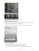
Configuring Interfaces on a Multi-Monitor Computer In EyStream, you can create several separate viewing tiles for display on additional physical monitors that are connected to a server or client. The number of separate tiles is equal to the number of connected physical monitors. If the system has more than one monitor connected, the monitor configuration panel is available on the Layouts tab. To create and configure a tile on an additional monitor: 1. Click on the monitor configuration panel.
The thumbnails may appear differently, depending on the status of the monitors in EyStream. Thumbnail Monitor status Main monitor Unassigned additional monitor Inactive additional monitor Active additional monitor 2. To activate an unassigned additional monitor in EyStream, click its thumbnail. The additional monitor becomes active and the layout of the main monitor is duplicated to it. 3. Configure the layout of the additional monitor.
Configuring how EyStream starts Configuring EyStream instead of the standard Windows OS shell Autorun of EyStream, instead of the standard Windows OS shell, is used in cases where you need to restrict access to computers running the digital video surveillance system, including preventing the launch of various applications, file copying and deletion, various Windows operations, and other non-standard use of the computers.
To configure autologon, complete the following steps: 1. Go to Settings Options User interface (1–2). 2. 3. 4. 5. Select the Autologon check box (3). From the Server list, select the Server you need to query for automatic authorization (4). Enter the user name and password to be used for automatic authorization (5). Click the Apply button. Configuration of autologon is now complete. Once EyStream is restarted, it will automatically connect to the selected Server under the specified user.
2. In the Period field, enter the amount of days to store the system log in the Server’s database and to store metadata in the object trajectory database (3). 3. In the appropriate field, enter the amount of hours after which outdated events will be purged from the system log (4). Outdated events are events that have been stored in the system log for a period greater than that indicated in step 2.
2. In the Path for snapshot export (3) and Path for video export fields (4), enter the full path to the folders where exported files are to be saved. To do this, click the button . Attention! If you modify the paths to exported file folders on one computer, those paths will also be changed on all computers in the EyStream Domain and on all Clients 3. If you need to automatically export snapshots while "freezing" video in real time, select the corresponding check box (5). 4. Click the Apply button.
2. The maximum allowed reaction time to an alarm is the length of time from the moment the operator who accepted an alarm for processing exits alarm mode, after which the alarm returns to New status, and the count for the allowed time for ignoring an alarm begins again. Note For example, an operator can exit alarm mode to view the video archive related to the alarm To configure alarm handling in the system, you must perform the following steps: 1. Go to Settings Options Alarm processing (1-2). 2.
3. Set the time intervals for the schedule: a. Enter the interval's start time in the From column with the help of the buttons accessible by left-clicking the appropriate cell twice (1). Button Action Shift the interval start back by 1 hour Shift the interval start back by 15 minutes Shift the interval start ahead by 15 minutes Shift the interval start ahead by 1 hour b. Enter the interval's end time in the To column with the help of the buttons accessible by left-clicking the appropriate cell twice (2).
4. Click the Apply button. Creation of a schedule is now complete. Deleting a schedule To create a schedule, complete the following steps: 1. Go to the list of schedules (under Settings Options Scheduled recording). 2. Click beside the schedule that you want to delete. 3. Click the Apply button. Deletion of a schedule is now complete. Creating and Configuring the Role and User System Objects In EyStream, only one role (Administrator) and one user (root) are registered default.
A role is intended for assigning a group of users individual rights and permissions for administration, management and/or monitoring of individual components of EyStream. To register a new role, perform the following: 1. Select a role in the user tree (1). 2. Bring up the context menu of the user tree by right-clicking the mouse. 3. Select Add role (2).
Microphone Telemetry Monitoring in Armed mode The image from the video camera can be viewed only when the video camera is armed. Archive is inaccessible. The user is unable to arm/disarm the video camera. Monitoring The user can view the image from the video camera. Archive is inaccessible. Monitoring and Archive The user can view the image from the video camera. Archive is accessible. Monitoring/Archive/Armed mode All functions are accessible.
2. Bring up the context menu of the user tree by right-clicking the mouse. 3. Select Delete role (2). 4. Click Apply to save the changes. The role has now been deleted. All users that were assigned the specified role will now be placed in the Unassigned group. The User Object In EyStream, several users can be assigned to one role. The user will be granted the permissions for administration, management and/or monitoring that are indicated in the settings of the role.
4. Enter the password in theSecurity configuration group (2). a. Click . The Change password window opens. b. Enter the user's assigned password in the New password field (1). c. Retype the assigned password in the Confirmation field (2). d. Click OK to save the settings. 5. Enter the user name in the Basic configuration group (3, User properties). 6. Select a role in the Basic configuration group (4, User properties).
2. Bring up the context menu of the user tree by right-clicking the mouse. 3. Select Delete user (2). 4. Click Apply to save the changes. The user has now been deleted from the user tree. Working with the EyStream Software Package Main Elements of the User Interface Viewing Tile A viewing tile is used to display video stream on the monitor of a computer with specific parameters for the purpose of video surveillance, archive viewing, and forensic search in archives.
Red Alarm for this camera Gray Archive mode Dark blue Snapshot function enabled Note Color coding for alarm status has priority over color coding for archive and snapshot modes. Viewing Tile Context Menu The viewing tile context menu is used to access the following functions (depending on the enabled surveillance mode): 1. 2. 3. 4.
In real-time mode, the time display shows the current time: . In archive, alarm, and video frame search modes, it shows the time of the fragment being viewed and the playback mode: 1. Forward playback . 2. Reverse playback . 3. Pause . The Snapshot function can be enabled in all video monitoring modes, with the help of the :time display. To do this, left-click in the area with the clock. A snowflake will now appear to the left of the clock. .
Video statistic Parameter description Client-side FPS Frame rate of the displayed video stream. Server-side FPS Frame rate of the video stream received from a video camera or an archive. Bitrate Bitrate of a compressed video stream. Frame size Resolution of the displayed video stream. Video Surveillance Mode Selection Tabs To select the video surveillance mode, use the tabs in the lower right-hand part of the viewing tile. 165 eLineTechnology.com 303.938.
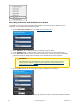
Color coding of tabs corresponding to inactive surveillance modes is disabled: 1. Live Video mode . 2. Alarm Management mode 3. Archive mode: . . 4. Archive Search mode: . The tab corresponding to the active surveillance mode is highlighted with a color: 1. Live Video mode . 2. Alarm Management mode 3. Archive mode: . . 4. Archive Search mode: . Layouts Layouts that have been created in the system are shown in the layouts ribbon.
Select the displayed layout To select a layout to display on a monitor, go to the layouts ribbon. Left-click the appropriate thumbnail, after which the selected camera layout is displayed. Layout slideshow Slideshow mode is rotation through all user-accessible layouts according to an assigned frequency (dwell-time). To launch slideshow mode, bring up the context menu of the layout ribbon, click the and select Start slideshow .
The size and resolution of the images is not limited. Please refer to the section titled Working with the Interactive Map for further details on how to work with the 3D map. The Archive Navigation Panel The Structure and Function of the Archive Navigation Panel The archive navigation panel is automatically displayed in the right-hand part of the screen when you switch the viewing tile to Archive or Search for Clip by Frame mode. The archive navigation panel includes the following components: 1.
4. Alarms list. 5. Playback panel. The archive navigation panel is used for the following functions: 1. 2. 3. 4. 5. 6. Navigating through the archive. Playing back recordings. Selecting playback mode: forward or backward. Setting playback speed. Selecting alarms for display on the timeline and in the alarm events list. Viewing the list of alarm events of the selected type.
The timeline is a graphical representation of the time axis of the archive and is located in the middle part of the navigation panel. The timeline contains indicators of the presence of recordings, or tracks. 170 eLineTechnology.com 303.938.
Tracks are marked in different colors depending on the alarm status or detection tool activation: Display of any particular alarm event in the list is determined by filter settings (see the section titled The Alarm Events Filter). Condition Color of the alarm period on the track Archive absent Dark Gray archive White Archive present, detection tool activated (no alarm) Orange Archive present, alarm active Red Note The colors of alarm periods overlap when they coincide in time.
The timeline's background can be displayed in two styles, depending on settings (see the section titled Configuring the timeline): 1. Day/Night 2. Shift work 172 eLineTechnology.com 303.938.
You can scroll and zoom the timeline using the mouse. To scroll the timeline, move the cursor on its background (displayed in the Day/Night or Shift work style) vertically while holding down the left mouse button. To change the scale of the timeline, right-click the timeline's background (Day/Night or Shift work) and, while holding down the right mouse button, move the cursor down to zoom out or up to zoom in.
Note You can also set a timeline indicator in the desired position by indicating the exact date and time (see the section titled Setting the timeline indicator in the desired position.). You can position the indicator with the help of the alarms list (see the section The alarms List). The Position Selection Panel The position selection panel is used for the following functions: 1. Setting the timeline indicator in the desired position. 2. Scrolling and zooming the timeline.
2. In this window, select the Set current position check box (2). The time parameters in the Set current position group, which determine the position of the timeline indicator, will become available for editing. 3. Position the cursor over the desired time parameter (day of the week, date, month, year, hour, etc.) (2). Arrows for increasing () and decreasing () the selected parameter then appear. To change the parameter by one unit, click the corresponding arrow once.
2. In this window, select the Set range check box (2). The time parameters in the Set range group, which determine the boundaries of the displayed section of the timeline, will become available for editing. 3. Set the From and To boundaries of the timeline in the same way as in step three of the section titled Setting the timeline indicator in the desired position.. Setting the timeline section results in the scrolling of the timeline. If you set a narrow section, the scale of the timeline will increase.
The alarms list is now displayed. 177 eLineTechnology.com 303.938.
Note Whether or not a particular alarm is displayed in the list depends on the filter settings (see the section The Alarm Events Filter). Note The alarm list displays only those alarm events that are currently present in the visible portion of the timeline. To hide the alarms list, click the alarms button again. When you place the cursor over an alarm in the list, detailed event information appears.
The playback panel contains the following buttons: 1. Go to preceding frame. 2. Go to next frame. 3. Switches to the preceding recording. 4. recording. 5. Switches to the next Play/Pause. The button also acts as a slider which sets the speed and mode (forward/backward) of playback. Note Use of the playback panel is described in detail in the section Navigating Using the Playback Panel. 179 eLineTechnology.com 303.938.
Advanced archive navigation panel The advanced archive navigation panel is automatically displayed in the lower portion of the viewing tile when you switch to Archive mode or Archive Search mode. The advanced archive navigation panel includes the following components: 1. Timeline 2. Playback control buttons 3.
when playback is restarted on the advanced navigation panel, and vice versa. 3. The playback control buttons on the advanced navigation panel are the same as the buttons on the playback panel. 4. Any movement through the main timeline is duplicated onto the timeline of the advanced navigation panel. The PTZ Control Panel The PTZ control panel is displayed automatically in the right-hand part of the screen when the viewing tile of a PTZ camera is activated in Live Video mode.
4. Virtual 3D joystick 5. Patrol button Note Use of the dialer, PTZ controls, joystick, and patrol button is described in the section Controlling a PTZ Camera. The Dialer Panel The dialer panel is used to switch to a PTZ preset. To display the dialer panel, click the Dialer button. The dialer panel will then be displayed on the PTZ control panel. The Dialer button: The Dialer panel: To hide the dialer panel, click the Dialer button again.
For each preset in the list, the following parameters are displayed: 1. The identification number 2. A descriptive name The presets list is used for the following functions: 183 eLineTechnology.com 303.938.
1. 2. 3. 4. Creating presets. Editing the identification number and name of an existing preset. Deleting presets. Switching to a preset. You can create up to 100 presets with numbers from 0 to 99. To create a preset, you must perform the following steps: 1. Place the PTZ camera in the position which is to be saved as a preset. 2. Click . Fields for entering an identification number and a descriptive name for the preset will then appear. 3. Fill in these fields as desired.
There are three modes for working with a viewing tile: 1. 2. 3. 4. Live Video mode alarm video mode Archive mode Archive Search mode Note Alarm Management mode is available if an alarm has been initiated in the system. Functions Available in All Video Surveillance Modes The following video surveillance functions are available in all video surveillance modes: 1. 2. 3. 4. 5. 6. Selecting a video camera. Scaling the viewing tile. Digitally zooming video images. Processing video images. Tracking objects.
Attention! In the archive and alarm management modes, clicking an event will switch the view to the live video mode. Selecting a Video Camera Using the Context Menu of the Viewing Tile To select a video camera using the context menu of the viewing tile, you must perform the following steps: 1. Bring up the context menu in the viewing tile (1). 2. Choose Camera selection (2). 3. Select the necessary video camera in the displayed list using one of the following methods: a.
The image from the selected video camera will now be displayed in the viewing tile. Selecting a Video Camera Using the Viewing Tile Preview Ribbon The video camera panel is used to display a list of video cameras linked to EyStream. Note By default, the video cameras panel does not display any video cameras (Not selected status) You can search for a camera either by: 1. Click the Not selected drop-down list (1) and select the necessary video camera group from the displayed list.
Note A video camera is displayed on the video camera panel only once. If you selected a group containing subgroups that all include a specific video camera, that video camera will be displayed on the video camera panel only once. Note If you selected a group containing subgroups, the video camera panel will display the video cameras included in that group as well as the cameras in all subgroups of that group.
Note In Archive Search mode, you can increase the size of the viewing tile by only one level. You can also use the mouse to scale the viewing tile. If the viewing tile is maximized to fill the entire screen, a double left-click of your mouse within the tile area will minimize the tile. Otherwise a double left-click will maximize the viewing tile to fill the entire screen.
Digital zoom scale: To enlarge a video image, left-click the slider and hold and drag the digital zoom scale up to the desired value. The maximum zoom is 16x. To return back to the original image, move the slider back to its original position. Note You can also use the and buttons to scale the video image. To hide the digital zoom scale, select Hide digital zoom in the context menu of the viewing tile.
You can select an area by doing the following: 1. Click and hold down the left mouse button inside the viewing tile. 2. Move the mouse cursor to the desired position. 3. Release the left mouse button. Once you have completed the above actions, the selected area will be displayed across the entire viewing tile. 191 eLineTechnology.com 303.938.
Note If you select an area that requires a zoom of more than 16x to display, it will be marked with a red frame. The video image will not be enlarged. Enlarging a video image using the mouse scroll wheel When using the mouse scroll wheel, the video image is enlarged relative to the mouse cursor. A description of this process is provided in the table below.
To enable video image processing functions, use the Visualization option in the context menu of the viewing tile. Only one image processing function can be enabled at a time. Changing the Contrast Level An EyStream operator is granted access to adjust the contrast of a video image. To adjust the contrast, select the Contrast option in the Visualization context menu. An example of the Contrast function is given in the following image. 193 eLineTechnology.com 303.938.
To return to the original image, reselect the Contrast option in the Visualization context menu. Setting the Sharpness Level An EyStream operator is granted access to adjust the sharpness of a video image. To adjust the sharpness, select the Sharpness option in the Visualization context menu. The image in the following picture shows an example of use of the Sharpness tool. 194 eLineTechnology.com 303.938.
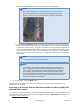
To return to the original image, use the Sharpness function again. Using Deinterlacing The Deinterlacing tool is used to correct tooth-type distortions (also called "combing artifacts"), which appear on the borders of video image fragments when objects move quickly relative to the background. An example of a combing artifact is shown in the picture below. To utilize this tool, select the Deinterlacing option in the Visualization context menu. The image in the viewing tile will then be corrected.
To disable Deinterlacing, reselect the Deinterlacing option. Tracking objects Object tracking allows a user to visually track the movement of objects in a camera's field of view or in a video recording in an archive. Attention! Object tracking is possible only if a situation analysis detection unit and/or an embedded detection unit is active (see the sections Situation Analysis Detection Tools and Embedded Analytics). Object tracking performs the following functions: 1.
Displaying the current sensor status To display the current status of a video camera’s sensor, select Show sensor in the context menu of the viewing tile. Note You must first activate an object to display the status of its sensor. The current status of the sensor will now appear in the viewing tile. Note To hide the sensor status, select Hide sensor in the context menu of the viewing tile. There are four possible statuses of a sensor.
To switch the viewing tile from a different surveillance mode to archive analysis mode, switch to the tab in the lower-right corner of the tile. The viewing tile will then appear in Live Video mode. Note The button turns green when real-time mode is enabled -> . Video Surveillance Functions Available in Live Video Mode In Live Video mode, the following video surveillance functions are accessible: 1. 2. 3. 4. 5. 6. 198 Selecting a video camera. Scaling the viewing tile. Digitally zooming video images.
7. 8. 9. 10. Arming/disarming a video camera. Taking snapshots. Controlling a PTZ Camera. Controlling relays. Note The following functions are accessible in all video surveillance modes: scaling the viewing tile, digital zoom, video image processing, Select video camera functio ns in the current tile and Object tracking.
This will cause the viewing tile to be highlighted with a blue border. A snowflake icon will appear in the Time field, and the Snapshot option will be replaced with Cancel snapshot in the context menu of the viewing tile. An example of using the Snapshot function Snowflake symbol: An example of using the Snapshot function Cancel snapshot option Snapshot: 200 eLineTechnology.com 303.938.