
Data Sheet

5
ETHERIO24TCPDATASHEET
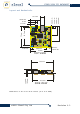
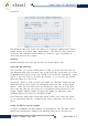
POWERCONNECTORS
TheModulehasa2.1mmDCjackthatisconfiguredasPositiveCentrepin
withgroundsleeve.TheDCJackismountedoverhangingtheboard’sedgein
orderthatthemodulecanbemountedwiththenetworkconnectorandpower
connectorprotrudingthroughacase.
Thereisanadditionalscrewterminalconnectionthatallowsforthe5v
supplyfromtheonboardregulatortobeusedtopowerusercircuitsand
sensors.Themaximumcurrentthatusercircuitsmaydrawfromtheon
boardregulatoris500mA;ifthiscurrentisexceededthentheoperation
oftheboardmaybeadverselyaffected.
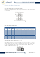
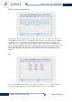
ETHERNETCONNECTOR
ThemoduleisequippedwithastandardRJ45networksocketandconformsto
the10Base‐Tstandard.Only4ofthe8wiresareusedfornetwork
interface,2asapairfordatasentfromthemoduleand2asapairfor
databeingreceivedbythemoduletheotherwiresareunusedatthistime.
18
EthernetConnector
PIN# NAME DESCRIPTION
1 TXD+ TransmitDataPositiveSignal
2 TXD‐ TransmitDataMinusSignal
3 RXD+ ReceiveDataPositiveSignal
6 RXD‐ ReceiveDataMinusSignal
PROGRAMMINGHEADERFORFACTORYPROGRAMMING(ICDHEADER)
Thisheaderisusedforfactoryprogramming,DONOTUSE
thisconnectorfor
anyotherpurpose.
LEDIndicators(NetworkLink/ACTandValidCommand)
Thereare2LEDindicatorlightsontheEtherIO24TCPmodule;their
operationisasfollows.
UPPERLED=NETWORKLINK/ACTIVITY.ThisLEDisilluminatedwhenthe
moduleispoweredandthenetworkinterfacehasdetecteda
connection.TheLEDwillblinkwheneverthereisactivityon
thenetworklink.
LOWERLED=VALIDCOMMAND.ThisLEDilluminateswhentheboardispowered
andwillturnoffeachtimetheunitprocessesavalidcommand.
Whenthecommandsarearrivingfasterthan10timespersecond
theLEDwillbeappeartobeswitchedoff.
©
2013ElexolPtyLtd Revision1.3