ETHER IO24 TCP DATASHEET ETHER IO24 TCP The Ether IO24 TCP (Originally named the Ether IO24 PIC R) is an integrated, micro‐controller based network interface board with 24 digital user I/O lines. The module’s firmware and hardware enable your devices or other modules to be connected to a generic Ethernet network and controlled using commands sent over the network via either TCP or UDP.
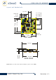
ETHER IO24 TCP DATASHEET Layout and Mechanicals 6.50 mm 20M00 63.5 mm 72 mm 35.68 mm 9 mm 17.3 mm 7.75 mm 30.6 mm 53.45 mm 2.64 mm 15.3 mm 50.9 mm All holes 3.5mm dia 72 mm TOP VIEW 72.0 mm 1.60 mm 13.4 mm 10.6 mm 75.5 mm SIDE VIEW Dimensions: 2.8 X 2.8 X 0.55 inches (72 X 72 X 14mm) ©2013 Elexol Pty Ltd Revision 1.
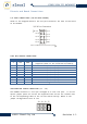
ETHER IO24 TCP DATASHEET Pinouts and Board Connections I/O PORT CONNECTIONS (10 PIN BOX HEADER) Shown in the diagram below is the I/O port Connector for each of the Ports on the module. I/O 24 Port Connection +5V I/O 7 I/O 6 I/O 5 I/O 4 I/O 3 I/O 2 I/O 1 I/O 0 GND Note: Pin1 Marked on I/O Accessory with IO24 BOX HEADER CONNECTIONS PIN # SIGNAL TYPE 1 +5V PWR 2 3 4 5 6 7 8 9 10 I/O 7 I/O 6 I/O 5 I/O 4 I/O 3 I/O 2 I/O 1 I/O 0 GND I/O I/O I/O I/O I/O I/O I/O I/O PWR DESCRIPTION +3.
ETHER IO24 TCP DATASHEET The table below outlines the jumper configurations JUMPER J1 J2 J3 J4 ©2013 DESCRIPTION ON – Lock EEPROM OFF – Allow EEPROM writes ON – Unit will DHCP for IP address, and all EEPROM values will be ignored this includes power up settings and any fixed IP programmed into the unit. OFF – Load all values from EEPROM, unit will load IP address if programmed or else it will DHCP Fixed IP address 10.10.10.10 given to unit and port number defaults to 2424 Fixed IP address 192.168.1.
ETHER IO24 TCP DATASHEET POWER CONNECTORS The Module has a 2.1mm DC jack that is configured as Positive Centre pin with ground sleeve. The DC Jack is mounted overhanging the board’s edge in order that the module can be mounted with the network connector and power connector protruding through a case. There is an additional screw terminal connection that allows for the 5v supply from the onboard regulator to be used to power user circuits and sensors.
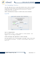
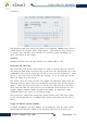
ETHER IO24 TCP DATASHEET Java Programming Interface The Ether IO24 TCP has an on board web interface that is used to configure all options for the module. This interface can be accessed via any java enabled web browser. The following section describes all features incorporated in the interface. MODULE CONFIGURATION AND POWER UP SETTINGS USING THE WEB INTERFACE Log‐in Tab Log‐in / Change Password Enter Password to log‐in. Factory default is a blank password. logged in, you can change the password.
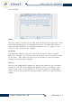
ETHER IO24 TCP DATASHEET Test Controls Value The port value is written to or read from the entire port with each of the value bits affecting the corresponding I/O line. The Auto read values check box when checked will constantly read Port A, B, C (poll) on the device to see if the pin has changed. Direction The Direction value of the port can be set as either input or output. When set as output, the I/O line will be driven to the last value written to the port.
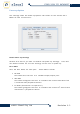
ETHER IO24 TCP DATASHEET Power‐up Options The settings under the Power‐up Options Tab relate to the various Port Modes of each of the Ports. Enable Power‐Up Settings Uncheck this box if you want to disable the power‐up settings. This will set default values for all the settings of the unit on power‐up. Port Modes Sets the Port modes for each port. These modes include: • IO Mode This mode sets the Port to a standard Input/output port.
ETHER IO24 TCP DATASHEET Value, Direction and Pull‐Up The module can be programmed to power up with all its ports to the pre‐ programmed state, thus if a machine needs to have certain devices enabled at power up or if the machine designer desires all lamps to light in a lamp test, it is possible for the module to accomplish this before the main control system is active. Listed below are the various settings that can be programmed for power up.
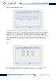
ETHER IO24 TCP DATASHEET AutoScan The AutoScan mode will allow the module to originate communication with a remote device or another Ether IO24 module. This mode is very useful as it allows your software the freedom not to have to poll the module to check the state of the inputs Protocol Enables AutoScan and sets the Protocol to either UDP or TCP.
ETHER IO24 TCP DATASHEET Bit Test Enables Mask bits are used to allow some of the input pins to toggle without generating messages from the module. Any input whose corresponding mask bit is low, is ignored by the AutoScan function. Port / Static IP / Timeout TCP Server Timeout Use this field to set the time (seconds), of inactivity on a TCP connection before the TCP Server closes the connection. Command Port Use this field to set the Command Port number.
ETHER IO24 TCP DATASHEET 12 Command Interface (Via TCP and UDP Packets) The functions of the module are controlled by a command set that is sent via TCP or UDP packets. These TCP and UDP packets can be sent out from the PC via application software or from other Ether IO24 module if using AutoScan. This section will cover in detail the command summary followed by the Command set used by the Ether IO24 TCP module.
ETHER IO24 TCP DATASHEET 13 Command Quick Reference Table 1, Module Command Set Command ASCII Command Hex Bytes Data Function Response Bytes Response Identifier IO24 0x49 0x4F 0x32 0x34 4 ‐ Identify IO24 Units 12 IO24 A B C a b c 0x41 0x42 0x43 0x61 0x62 0x63 2 2 2 1 1 1 Port Value Port Value Port Value ‐ ‐ ‐ ‐ ‐ ‐ 2 2 2 ‐ ‐ ‐ A B C Response Data 6 Byte MAC Address 2 Byte Firmware Version ‐ ‐ ‐ Port A Value Port B Value Port C Value !A 0x21 0x41 3 Direction ‐ ‐ ‐ !B 0x21 0x42
ETHER IO24 TCP DATASHEET Overview of Command Set Identify Ether IO 24 Units Command Sent Command Reply ASCII Code Bytes Data IO24 4 ‐ ASCII Code Bytes IO24 12 Function Used to identify/find modules on the network and send specific module information (MAC address) Data 6 Bytes being the Modules’ MAC Address 2 Bytes being the Modules’ Firmware Version Operation: This Operation is used to find modules on the network as the module will respond to this command when broadcast.
ETHER IO24 TCP DATASHEET Operation: Same operation as Write Port A Register but implemented on Port C Read Port Value Read Port A Command Sent Command Reply ASCII Code Bytes Data a 1 ‐ ASCII Code Bytes Data A 2 Port‐Value Function Sends the Value of Port A back to the host Operation: The Value of the 8 I/O lines of Port A is read and sent back to the host. Those pins that are set as outputs are read as though they were inputs and their values sent back in the Port Value Byte.
ETHER IO24 TCP DATASHEET Write Port Direction Register Write Port A Direction Register ASCII Code !A Bytes 3 Data Direction Function Writes data to port’s direction register. Lines with a corresponding bit value of 0 are set as outputs, lines with a bit value of 1 are set as inputs The power up default for Direction is 255 setting all lines as inputs Operation: This command affects all eight lines of port A.
ETHER IO24 TCP DATASHEET Read Port Direction Register Read Port A Direction Register Command Sent Command Reply ASCII Code Bytes Data !a 2 ‐ ASCII Code Bytes Data !A 3 Function Sends the Direction Register value back to the host Register‐ Value Operation: The Direction Register of Port A is read and its value sent back to the host.
ETHER IO24 TCP DATASHEET Write Port Pull‐up Register Write Port A Pull Up Register ASCII Code %A Bytes 3 Data Function Enable Writes data to port’s direction register. Lines with a corresponding bit value of 1 have their pull up resistors turned on, lines with a bit value of 0 have their pull up resistors turned off The power up default for Enable is 0; all pull up resistors turned off Operation: This command affects all eight lines of port A whose direction is set as an input.
ETHER IO24 TCP DATASHEET Read Port Pull‐up Register Read Port A Pull Up Register Command Sent Command Reply ASCII Code Bytes Data %a 2 ‐ ASCII Code Bytes Data %A 3 Function Sends the Pull Up Register value back to the host Register‐ Value Operation: The Pull Up Register of Port A is read and its value sent back to the host.
ETHER IO24 TCP DATASHEET High/Low Commands Raise IO Pin (High) ASCII Code Bytes Data H 2 IO Pin Number Function Raises the IO pin indicated by IO Pin Number (Numbered 0 to 23) Operation: This command Raises the Pin Value on the IO Pin indicated in IO Pin Number. IO Pin Number is a number between 0 and 23 where Port A Pins correspond to 0 ‐ 7, Port B Pins correspond to 8 ‐ 15, and Port C Pins correspond to 16 ‐ 23. The corresponding IO Pin must be set to Output for this command to have effect.
ETHER IO24 TCP DATASHEET Write EEPROM ASCII Code Bytes ‘w 5 Data Function AddMSB AddLSB The Data value is written to the EEPROM address at AddMSB:AddLSB Data Operation: The module will write the EEPROM memory at the specified Address with the data contained in the Data byte. Special Conditions: The EEPROM cannot be written if the J1 pin is tied to GND.
ETHER IO24 TCP DATASHEET Serial Communications Modes (Via I/O Ports) Serial Communications Modes include SPI Mode and I2C Mode. The Port Mode is set as part of the Power‐up Options in the Ether IO24 TCP Java Applet. Once the Mode is set, all communications are done using the S Command as set out below.
ETHER IO24 TCP DATASHEET SEND SERIAL DATA ON PORT B Command Sent Command Reply (SPI Mode) Command Reply (I2C Mode)1 ASCII Code Bytes Data SB 2 + #data bytes + data #data bytes + data ASCII Code Bytes Data 2 + #data bytes + data SB Return data ASCII Code Bytes Data SB 2 + #data bytes + data Return data 1 Function Sends out Serial* data on PORT B. The number of data bytes is sent out first followed by the data.
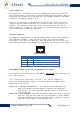
ETHER IO24 TCP DATASHEET Overview of SPI Mode The SPI interface that is implemented on the Ether IO24 TCP is a very basic SPI master device that allows 4 different modes. The SPI mode only has the one clock speed which is mentioned below in the specifications. The SPI interface can be used to communicate with A/D, GPIO Expander, EEPROM chips to name a few. Shown in the diagram below is the typical connection of an SPI device to the Ether IO24 TCP.
ETHER IO24 TCP DATASHEET SENDING BYTES VIA SPI To send out SPI data on Port A the command that needs to be sent out requires an "SA" prefix followed by the number of bytes you want to send followed by the data stream. To send out the following bytes 0xFF 0xAA 0x55 you would send the following "SA" + 0x03 + 0xFF + 0xAA + 0x55 RECEIVING BYTES VIA SPI Receiving byte that number of been sent bytes via SPI happens when the bytes are sent out, for every is clocked out, there is an incoming byte being received.
ETHER IO24 TCP DATASHEET BASIC OVERVIEW OF SERIAL COMMUNICATIONS TO SPI ACCESSORY BOARDS Listed below is a basic overview of the procedure that needs to be followed in order to communicate with the board. 1. Configure the Port for SPI Mode using the Web‐based Java Application. 2. Setup Port Values on Ether IO24 TCP for idle state on SPI Board 3. Lower the CS pin for chip communication 4. Start SPI communication by sending start byte 5. Send Control Byte or write command registers 6.
ETHER IO24 TCP DATASHEET SPI SPECIFICATIONS The table below outlines the specifications of the SPI mode implemented on the Ether IO24 TCP.
ETHER IO24 TCP DATASHEET Overview of I2C Mode The I2C interface that is implemented on the Ether IO24 TCP is a very basic I2C master. The I2C mode only has the one clock speed which is mentioned below in the specifications. The I2C interface can be used to communicate with A/D, GPIO Expander, EEPROM chips to name a few. Shown in the diagram below is the typical connection of an I2C device to the Ether IO24 TCP.
ETHER IO24 TCP DATASHEET AutoScan Configuration The AutoScan mode will allow the module to originate communication with a remote device or another Ether IO24 module. This mode is very useful as it allows your software the freedom to not have to poll the module to check the state of the inputs. An overview of the AutoScan settings can be found in the AutoScan section of the Web Interface Chapter above.
ETHER IO24 TCP DATASHEET EEPROM Configuration The EEPROM number and the module data to be on the Ether IO24 TCP is used to store the board’s Serial other critical factory settings as well user settings for and there is even a spare area where you can store your own kept by the module, even when the module loses power. The EEPROM on the Ether IO24 TCP is used to store the configuration settings for the board.
ETHER IO24 TCP DATASHEET Coding Examples The example code has been written in Visual C# Express and are available for download from our website www.elexol.
ETHER IO24 TCP DATASHEET Closing TCP Connection //******************************************************************** //TCP Disconnect function closes port //******************************************************************** private void TCPDisconnect() { client.Close(); client = null; TestTextBox.
ETHER IO24 TCP DATASHEET READING PORT VALUE //******************************************************************** //TCP Read Port function sends the command to the device, //to read the Port and the Value on the Port //******************************************************************** private void TCPReadPort_Click(object sender, EventArgs e) { //******************************************************** //Define the Return Buffer for incoming data //********************************************************
ETHER IO24 TCP DATASHEET //******************************************************************** //TCP Read PortValue function Reads the icoming datastream from the device, //the data returned is the Port and the Value //******************************************************************** private byte[] ReadPortValue(NetworkStream clientStream) { //******************************************************** // Define variables that are to be used in routine //***************************************************
ETHER IO24 TCP DATASHEET //******************************************************************** // HandelClientComm() // This method runs in the client thread. // It will handle data coming from the client and loop until // the client disconnects. //******************************************************************** private void HandleClientComm(object client) { TcpClient tcpClient = (TcpClient)client; NetworkStream clientStream = tcpClient.
ETHER IO24 TCP DATASHEET UDP INTERFACE EXAMPLES Sending UDP Commands BROADCAST IO24 Shown below is example code for a button (Ether_Scan) that broadcasts “IO24” on port 2424 using System; using System.Collections.Generic; using System.ComponentModel; using System.Data; using System.Drawing; using System.Linq; using System.Text; using System.Windows.
ETHER IO24 TCP DATASHEET SETTING PORT DIRECTION REGISTERS AND PORT VALUES The example code below shows the button code for setting the Port Direction register and the port values for PORT A on the Ether IO24 TCP. The ‘A’ can be replaced with ‘B’ or ‘C’ depending on which port is being used.
ETHER IO24 TCP DATASHEET Receiving UDP Command Responses UDP LISTENER This example program will broadcast IO24 across the network on start up and list all Ether IO24’s that respond to the command in a drop down combo box. using System; using System.Collections.Generic; using System.ComponentModel; using System.Data; using System.Drawing; using System.Linq; using System.Text; using System.Windows.
ETHER IO24 TCP DATASHEET public void RecieveThread() { while (true) { //*********************************************** //Declare RemoteIPEndPoint //where RemotIPEndPoint is the any IP address //and Port Number of the incoming UDP packet //*********************************************** System.Net.IPEndPoint RemoteIpEndPoint = new System.Net.IPEndPoint(System.Net.IPAddress.
ETHER IO24 TCP DATASHEET public void ReturnUDPData(byte[] UDPData, IPEndPoint RemoteIP) { //************************** //Declare Variables //************************** string MacString; string VersionNumber; //******************************************************* //if 12 bytes were recieved in UDP Packet from the device //then we have recived IO24 + MAC +Version //******************************************************* if ((UDPData.Length == 12)) { if (this.comboBox1.
ETHER IO24 TCP DATASHEET private void Ether_Scan_Click(object sender, EventArgs e) { //****************************************************** //Send out IO24 via broadcast(255.255.255.255) on port 2424 //****************************************************** //****************************************************** //fill sendBytes buffer with "IO24" //****************************************************** sendBytes = Encoding.ASCII.
ETHER IO24 TCP DATASHEET Absolute Maximum Ratings Warning! Exceeding these ratings may cause irreparable damage to the unit. Parameter Storage Temperature Ambient Temperature (Power Applied) Humidity Range Power Supply Input Voltage DC Input Voltage – Port Inputs DC Input Current – per IO Pin DC Output Current – per IO Pin DC Input Current – Total per Port DC Output Current – Total per Port Absolute Maximum Conditions ‐65°C to +150°C ‐40°C to + 75°C 0 to 85 %RH +7v to +35.00v DC ‐0.6v to +5.
ETHER IO24 TCP DATASHEET Technical Support For any questions relating to the Ether IO24 TCP or if we can assist you with integrating the Ether IO24 TCP into your own equipment please contact us by email at support@elexol.com Document Revision History • • • • Ether IO24 TCP Revision 1.1 – Revision 1.2 – Revision 1.3 – Datasheet Revision 1 – Initial document created Added AutoScan Section, Revised EEPROM Commands Corrected Absolute maximum Ratings Product name changed to Ether IO24 TCP.
ETHER IO24 TCP DATASHEET an Elexol Ether IO24 TCP module is hereby limited, at discretion of Elexol Pty Ltd, to replacement or repair. ©2013 Elexol Pty Ltd Revision 1.