
Data Sheet

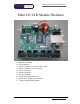


Ether I/O 24R Users Manual V1.1
Elexol Pty Ltd Version 1.1 Page 6 http://www.elexol.com
ELEXOL
ELECTRONIC SOL UT IONS
Functional Description
The Ether I/O 24 is an integrated, micro-controller based network interface board with 24 digital
user I/O lines and an on board switch mode voltage regulator. The module’s firmware and
hardware enable your devices or other modules to be connected to a generic Ethernet network and
controlled or sensed using industry standard protocols. Each of the 24 User I/O lines operates at
5V DC maximum levels and can be independently programmed as, an Input whose state can be
remotely sensed via another network device, an Input whose state is internally checked and
transmitted when a change occurs, or an output whose state can be remotely controlled by another
networked device.
The IP Address of the module is determined either automatically by BOOTP protocol from a
DHCP server or is programmed by the user to be at a fixed address. The MAC or Ethernet
address of the module is factory programmed and cannot be altered by the user.
Onboard firmware reads the user configuration stored on the module’s onboard non-volatile
memory and sets the ports to a user configured state at power up. If un-configured, all ports will
be set as inputs with the input thresholds set at TTL levels and the pull-up function disabled.
If configured to do so, the module periodically scans any or all of the digital inputs, filters any
changes to remove noise and signals a remote unit of the changes. The scan rate can be set from
1 millisecond to 65.5 seconds and the filter can be set to discard any number of unstable readings
from 1 up to 255. Each of the 24 signal lines has an independent control bit that controls whether
the module detects changes on that line. Filtering is done on a per port basis with each port
filtered as a group. When any line is set as an output its state is not checked for changes.
If a PC controls the module, the Programmer must have access to an UDP/IP socket in order to
communicate with the module. The Winsock control in MS Windows operating systems provides
for such communication in a simple and easy manner. As other operating systems have different
methods of programming network sockets, please consult your operating system’s specifications,
software and language manuals for details of how to open a UDP/IP socket to communicate with
the module.
The programmer should note that the UDP/IP protocol requires an IP address and a Port Number
to allow communication with the module. The Port number for communication with the module
is 2424 decimal and this port number is used for all UDP/IP communications for module and port
programming. Other port numbers are used for the ICMP and BOOTP protocols, however the
programmer is advised not to use other ports unless they possess an extensive knowledge of these
protocols.
The IP address of the module can be programmed to a fixed address by a windows PC running
the ELEXOL Ether I/O 24 Test and Programming utility software (downloadable from the Elexol
website). Alternately, the user may program the fixed IP address from their own software by
using the EEPROM writing commands. If the Fixed IP address function is not used the module
will have a dynamically assigned IP address from the DHCP server. To find the IP address of any
module, broadcast a special message to port 2424 and each of the Ether I/O 24 modules will
respond, stating their IP address, Ethernet address and firmware version number.
LED Functions
There are 2 LED indicator lights on the Ether I/O 24 module; their operation is as follows.
UPPER LED = NETWORK LINK/ACTIVITY. This LED is illuminated when the module is powered and
the network interface has detected a connection. The LED will blink whenever there is
activity on the network link.
LOWER LED = VALID COMMAND. This LED illuminates for 0.1 second each time the unit processes a
valid command. When the commands are arriving faster than 10 times per second the
LED will be continuously illuminated.