
Data Sheet

Ether I/O 24R Users Manual V1.1
Elexol Pty Ltd Version 1.1 Page 35 http://www.elexol.com
ELEXOL
ELECTRONIC SOL UT IONS
Basic Programming (continued)
6. Programming the Input options
All 24 lines of the module can be independently programmed with 6 different input options or be set as an
output. These input options are listed below with a brief description of each.
TTL Input: An input signal voltage below 1.4V reads as a low, above 1.4V reads as high
CMOS Input: An input signal voltage below 2.5V reads as a low, above 2.5V reads as high
Schmitt Trigger: An input signal below 0.25V reads as low, above 4.25V reads as high with any value in
between these values having no effect on the inputs status.
Pull Up: Any of the three modes listed can be enhanced by turning on an internal pull-up resistor
within the module thus removing the need for an external pull-up resistor. This feature
allows any contact or open collector output device to be connected to the module without
additional external components.
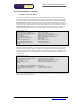
Three registers for each port, The Threshold Register, Schmitt Trigger Register and Pull-UP Register,
control the six different input modes. The Threshold Register sets whether the input threshold voltage is
1.4V or 2.5V: if the corresponding bit in the register is high then the threshold voltage is 1.4V and if low,
the threshold voltage is 2.5V. The Schmitt Trigger Register overrides the threshold register when the
corresponding bit is low, enabling the Schmitt Trigger input state. Finally, the Pull-Up register enables the
corresponding pull-up resistor when the bit is low. The default power-up state for all registers is all high bit
(TTL Input, No Pull-Up) unless the EEPROM has been programmed to set them up differently.
There are 9 commands that correspond to the 3 input option registers for the three ports. The use of these
commands is exactly the same as the direction register except that the port letter prefix changes.
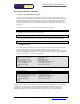
If for example we had 8 switches on Port C and we wanted these switches to be read by the module we
would probably choose to use the CMOS input mode with the Pull-Up resistors turned on. To achieve this
we would program the Threshold Register to all low bits and the Pull-Up register to all low bits with the
Schmitt Trigger Register as all high bits and the Direction register as all high bits.
PortC_Direction = 255
PortC_PullUp = 0
PortC_Threshold = 0
PortC_SchmittTrigger = 255
Winsock1.SendData "!C" + Chr$(PortC_Direction) + "@C" + Chr$(PortC_PullUp) + "#C" + Chr$(PortC_Threshold) + "$C"
+ Chr$(PortC_SchmittTrigger)
Once again, we have combined the four commands into a single packet thereby saving network traffic.
Whenever possible, combine all your set-up commands into a single data packet whereby processing
overhead will be lower and the module will be initialised more quickly.