
Data Sheet

Ether I/O 24R Users Manual V1.1
Elexol Pty Ltd Version 1.1 Page 31 http://www.elexol.com
ELEXOL
ELECTRONIC SOL UT IONS
EEPROM Memory contents
The EEPROM on the Ether I/O 24R is used to store the board’s Serial number and other critical
factory settings as well user settings for the module and there is even a spare area where you can store
your own data to be kept by the module, even when the module loses power.
The EEPROM chip on the module is 1 Kilobit in size or 1024 bits of memory; this is arranged as 64
words of 16 bits each. The first 5 words as addresses 0 to 4 are not user write-able. Words 5-24 are
currently used to store the user settings like fixed IP address, port power-up settings and AutoScan
mode settings. Words 25-47 are reserved for future use and words 48-63 are free for your own data
storage.
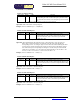
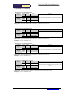
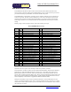
Memory Usage is shown by Byte for Clarity, each word is made up of 2 bytes.
Table 2, EEPROM Memory Usage
Word MSB
Byte
Function LSB
Byte
Function
0-4
1-9
Reserved (Unwritable)
0-8
Reserved (Unwritable)
5
11 Control Bits 2 10 Control Bits 1
6
13 Fixed IP Address Byte 2 12 Fixed IP Address Byte 1
7
15 Fixed IP Address Byte 4 14 Fixed IP Address Byte 3
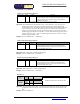
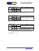
8
17 Preset Port A Value 16 Preset Port A Direction
9
19 Preset Port A Pull up 18 Preset Port A Threshold
10
21 Preset Port B Direction 20 Preset Port A Schmitt Trigger
11
23 Preset Port B Threshold 22 Preset Port B Value
12
25 Preset Port B Schmitt Trigger 24 Preset Port B Pull up
13
27 Preset Port C Value 26 Preset Port C Direction
14
29 Preset Port C Pull up 28 Preset Port C Threshold
15
31 Reserved for Future Use 30 Preset Port C Schmitt Trigger
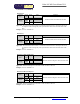
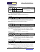
16
33 AutoScan Port B Mask 32 AutoScan Port A Mask
17
35 AutoScan Filter Count 34 AutoScan Port C Mask
18
37 AutoScan Scan Rate MSB 36 AutoScan Scan Rate LSB
19
39 AutoScan Target MAC Address 2 38 AutoScan Target MAC Address 1
20
41 AutoScan Target MAC Address 4 40 AutoScan Target MAC Address 3
21
43 AutoScan Target MAC Address 6 42 AutoScan Target MAC Address 5
22
45 AutoScan Target IP Address 2 44 AutoScan Target IP Address 1
23
47 AutoScan Target IP Address 4 46 AutoScan Target IP Address 3
24
49 AutoScan Target Port MSB 48 AutoScan Target Port LSB
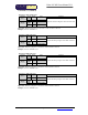
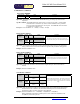
25
51 Subnet Mask IP Address 2 50 Subnet Mask IP Address 1
26
53 Subnet Mask IP Address 4 52 Subnet Mask IP Address 3
27
55 Gateway IP Address 2 54 Gateway IP Address 1
28
57 Gateway IP Address 4 56 Gateway IP Address 3
29
59 Programmable Port MSB 58 Programmable Port LSB
! Words 30 to 47 are reserved for future use and must be left erased to all ones !
Words 48 to 63 are for your own use and may be used for any function you desire.
The Control Bits 1 Location is used to turn on and off the Fixed IP address, Preset Port and AutoScan
mode functions. When the EEPROM is blank it reads all ones i.e. each blank word reads 65535 or
$FFFF. Because of this we use a 0 bit value to turn a function on. The currently used bits are bit 0,
which is used to enable the Fixed IP address, Bit 1, which is used to enable the Preset Port function and
Bit 2, which is used to enable the AutoScan function. All the remaining bits should be left as ones for
future compatibility as the firmware is upgraded and additional functions added.
Setting the Control Bits 1 byte to 255 turns off all three functions. The Fixed IP function has a bit
value of 1, the Preset Port function a bit value of 2 and the AutoScan function a bit value of 4. Simply
subtract the bit values of all the functions you wish to enable from 255 to calculate the value to write to
the Control Bits 1 Location.