
Data Sheet

Ether I/O 24R Users Manual V1.1
Elexol Pty Ltd Version 1.1 Page 30 http://www.elexol.com
ELEXOL
ELECTRONIC SOL UT IONS
SPI Mode
Notes on SPI
Bit 1 is always Clock and must be set as an output from the SPI to function
Bit 2 is always Serial Data Out (MOSI) and must be set as an output from the SPI to function
Bit 3 is always Serial Data In (MISO) and must be set as an input from the SPI to function
All other port pins act as normal
Setting the port pin as high or low will set the clock as normally high or low before the SPI
transaction begins.
Any of the other pins can be used as SS or CE when SPI is used.
Setting up SPI
1. Set PORTA direction register and data register to appropriate values for Chip select pins or
other pins that will be used by PORTA.
Winsock1.SendData “!A” + Chr$(Direction)
Winsock1.SendData “A” + Chr$(Value)
2. Send command Enable SPI on PORTA
Winsock1.SendData “S1A”
This will set the direction register of bits 0-2 to the appropriate value for SPI.
3. Sending bytes out via SPI
To send out SPI data on Port A it requires and "SA" prefix followed by the number of bytes
you want to send followed by the data stream. If you wanted to send out the following bytes
$FF $AA $55 you would do the following
Winsock1.SendData "SA" + Chr$(&H3) + Chr$(&HFF) + Chr$(&HAA) + Chr$(&H55)
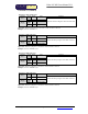
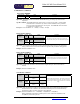
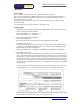
4. Receiving Bytes from SPI.
The number of bytes returned is determined by the number of bytes sent. Therefore if more
data is expected than what was sent out then Null bytes will have to be sent out. Sending out
the Null bytes is required to keep the SPI clock running so that the return data is clocked out
from the SPI slave device. There are null bytes sent in the example image below, this can be
seen in the last two bytes which are sent (implemented with don't cares) and on the input pin
you will have the valid data from the device. The valid data will be sent back in the command
response packet.
Note: you may have to send out leading zero's and don't cares depending on device you are
communicating with. e.g. seven leading zero's then a start bit as per the image below.
Example image for SPI communications with the MCP3004/3008 using 8 bit segments taken
from the MCP3004./3008 datasheet. (http://www.microchip.com)