
Data Sheet

Ether I/O 24R Users Manual V1.1
Elexol Pty Ltd Version 1.1 Page 16 http://www.elexol.com
ELEXOL
ELECTRONIC SOL UT IONS
Command Summary
For ease of use we have broken the command set into subgroups based on their function.
All commands are shown as their ASCII characters, text in italics represent binary 1 byte
values.
Values that pertain to port Input, Output or control are shown as data, values that pertain to
address information are shown as address and values that represent 16-bit information are
shown as MSB and LSB. When a byte is required as padding or for future use it is shown as
dummy. Where a specific byte is required its hexadecimal value is shown with a dollar sign
thus $55.
The spaces shown are only for clarity and no actual spaces are used in commands sent to the
module.
Example Code
All example code is written in Visual Basic with the Winsock control named Winsock1. To execute these
commands you will need to Place a Winsock component on your form and set the following option.
Winsock1.Protocol = sckUDPProtocol
Other options will be discussed further in the text
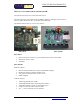
The I/O lines are accessed as 3 ports and each line is controlled by its bit value within the data byte.
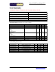
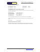
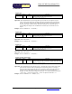
Port I/O Commands
Function Command Reply
Write Port A A data
Write Port B B data
Write Port C C data
Read Port A a A data
Read Port B b B data
Read Port C c C data
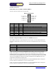
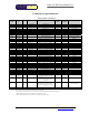
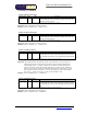
Port Configuration Commands
For each of the three I/O ports there are 4 commands used to set the ports’ options. First and
most critical of these options is Direction, which can be set as input or output. When set as
output, the I/O line will be driven to the last value written to the port. This value can be pre
set by writing to the port before writing to the direction register. When set as an output, none
of the other configuration commands have any effect. The Pull Up configuration command
applies to those lines that are set as inputs, writing a 0 to the corresponding bit applies a pull
up resistor to the line so that if it is not driven low it will be pulled to a known high state, this
is very useful if sensing contact closures or open collector outputs. The threshold function
sets the threshold at which a line reads as high or low. When the corresponding bit is set as 1
then the threshold is set at 1.4V and any voltage above this reads as a high level. When the
corresponding threshold bit is set to 0 the threshold is set at 2.5V and any voltage above this
reads as a high level. Last of the configuration commands allows the port to read as Schmitt
trigger inputs which means that the input line is compared to 2 voltages, 0.75V and 4.25V.
When the line’s voltage drops below 0.75V it will read as a low until the line’s voltage rises
above 4.25V at which time the line will read as a high. When the lines’ voltage is in between
0.75V and 4.25V, the value will remain stable at its previous level. To enable the Schmitt
trigger on any input a 0 must be written to the corresponding bit.
Write Direction A !A data
Write Direction B !B data
Write Direction C !C data
Write Pull Up A @A data
Write Pull Up B @B data
Write Pull Up C @C data