
Data Sheet

Ether I/O 24R Users Manual V1.1
Elexol Pty Ltd Version 1.1 Page 15 http://www.elexol.com
ELEXOL
ELECTRONIC SOL UT IONS
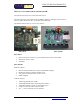
Module Connections (continued)
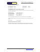
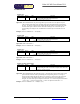
Ether I/O 24 Factory Programming Header (SX_PROG)
This header is used for factory programming, DO NOT USE this connector for any other
purpose.
Power Connectors
The Module has 2 types of power in connector; these connectors are connected directly to each
other. The 2.1mm DC jack is mounted overhanging the boards edge in order that the module can
be mounted with the network connector, power connector and status LEDs protruding through a
case. The second power connector or 5V from the module can then be used to power your own
circuitry. If the module is not mounted through a panel either or both of the power in connectors
may be used.
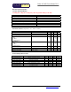
5V Out Screw Terminal Block (optional)
This terminal block, if fitted allows for the 5v supply from the onboard regulator to be used to
power user circuits and sensors. The maximum current that user circuits may draw from the on
board regulator is 500mA; if this current is exceeded then the operation of the board may be
adversely affected.
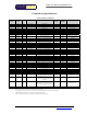
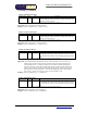
Ethernet Connector
The module is equipped with a standard RJ45 network socket and conforms to the 10 Base-T
standard. Only 4 of the 8 wires are used for network interface, 2 as a pair for data sent from the
module and 2 as a pair for data being received by the module the other wires are unused at this
time.
18
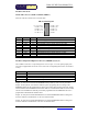
Ethernet Connector
Pin # Name Description
1 TXD + Transmit Data Positive Signal
2 TXD - Transmit Data Negative Signal
3 RXD + Receive Data Positive Signal
6 RXD - Receive Data Negative Signal
Pins 4, 5, 7 and 8 not used