E L E E L E C T R O N I C X O S O L U T Ether I/O 24R Users Manual V1.1 L I O N S ELEXOL Ether I/O 24 R Users Manual Version 1.1 For Firmware Release 2.0 Elexol Pty Ltd Version 1.1 Page 1 http://www.elexol.
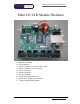
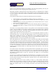
E L E X O E L E C T R O N I C S O L U T Ether I/O 24R Users Manual V1.1 L I O N S Ether I/O 24 R Module Hardware IÆ ÅD HÆ ÅC ÅB JÆ ÅA E A. B. C. D. E. F. G. H. I. J. F G Ethernet Connector LED Indicators Power Connector 2.1mm DC Jack Center + Power Connector Screw Terminal Port A Connector Port B Connector Port C Connector CONFIG Jumper Links J1-J4 Optional 5V output screw terminal Factory Programming Header Elexol Pty Ltd Version 1.1 Page 2 http://www.elexol.
E L E E L E C T R O N I C X O S O L U T Ether I/O 24R Users Manual V1.1 L I O N S Table of Contents Contents.............................................................................................................................................................. 4 Technical Support and Further Information ...................................................................................................... 4 Functional Description..................................................................
E L E E L E C T R O N I C X O S O L U T Ether I/O 24R Users Manual V1.1 L I O N S Contents When your Ether I/O 24 module arrives you should receive the following items. 1 2 The Ether I/O 24 Module in a Protective Anti Static Bag 2 Jumper Links (please note that these links may be factory fitted to the CONFIG connector on the board) Please inspect the Module carefully for any damage that may have occurred during shipping or handling.
E L E E L E C T R O N I C X O S O L U T Ether I/O 24R Users Manual V1.1 L I O N S Introduction Thank your for purchasing the Ether I/O 24 Module. We trust that programming and using the Ether I/O 24 will prove to be an ongoing positive experience for you. Please take a moment to unpack and inspect your module to ensure it is undamaged and is complete with the items listed in the contents section.
E L E E L E C T R O N I C X O S O L U T Ether I/O 24R Users Manual V1.1 L I O N S Functional Description The Ether I/O 24 is an integrated, micro-controller based network interface board with 24 digital user I/O lines and an on board switch mode voltage regulator. The module’s firmware and hardware enable your devices or other modules to be connected to a generic Ethernet network and controlled or sensed using industry standard protocols.
E L E E L E C T R O N I C X O S O L U T Ether I/O 24R Users Manual V1.1 L I O N S Accessory Boards In order to connect devices that are not 5V operated or require isolation, ELEXOL has pre-built accessory boards available. All accessory boards are equipped with box headers matching those on the Ether I/O 24 module and are supplied with 30cm long connecting cables. All external connections to the input or output channels of the accessory boards are by screw terminals that will accept cables 0.
E L E E L E C T R O N I C X O S O L U T Ether I/O 24R Users Manual V1.1 L I O N S Application Features The Ether I/O 24 has many unique features that enable its use in a great many applications. This section will describe what makes the module ideal for many real world situations. Why should I use Ethernet? Ethernet is the most prolific, most quickly growing and most common network standard in the world. Over 50 million pieces of equipment are already installed on this network.
E L E E L E C T R O N I C X O S O L U T Ether I/O 24R Users Manual V1.1 L I O N S Industrial Automation and Distributed I/O (continued) Fixed IP. Fixed IP addressing allows each module to be given a specific address that remains constant throughout the life of the machine thereby simplifying machine software design and allowing easy diagnosis of machine wiring faults. Electrical Isolation.
E L E E L E C T R O N I C X O S O L U T Ether I/O 24R Users Manual V1.1 L I O N S Home, Office and Building Automation, Distributed control and Internet Connectivity Because of its low cost per I/O line, the Ether I/O 24 module ideally services the budget sensitive building automation market.
E L E E L E C T R O N I C X O S O L U T Ether I/O 24R Users Manual V1.1 L I O N S Digital I/O from PCs Ethernet is now standard on almost all PCs making it an attractive option for the connection of I/O devices. In the past, using Ethernet for I/O has been too expensive or complicated. The Ether I/O 24 now changes that situation with the cost of Ethernet I/O now similar to that of USB solutions.
E L E E L E C T R O N I C X O S O L U T Ether I/O 24R Users Manual V1.1 L I O N S Differences between Ether I/O 24 and Ether I/O 24R The Ether I/O 24 R is the next version of the Ether I/O 24. The End of life notice on the SX52 due to Non RoHS compliance / Packaging issues has forced Elexol to update the Ether I/O 24 to incorporate the Parallax SX48.
E L E E L E C T R O N I C X O S O L U T Ether I/O 24R Users Manual V1.1 L I O N S Electrical Characteristics Absolute Maximum Ratings Warning! Exceeding these ratings may cause irreparable damage to the unit. Parameter Storage Temperature Ambient Temperature (Power Applied) Power Input Voltage DC Input Voltage – Inputs DC Output Current – Outputs DC Output Current – Total all outputs Maximum DC current into an input pin Power Dissipation Absolute Maximum Conditions -65°C to +150°C 0°C to + 70°C -1.
E L E E L E C T R O N I C X O S O L U T Ether I/O 24R Users Manual V1.
E L E E L E C T R O N I C X O S O L U T Ether I/O 24R Users Manual V1.1 L I O N S Module Connections (continued) Ether I/O 24 Factory Programming Header (SX_PROG) This header is used for factory programming, DO NOT USE this connector for any other purpose. Power Connectors The Module has 2 types of power in connector; these connectors are connected directly to each other. The 2.
E L E E L E C T R O N I C X O S O L U T Ether I/O 24R Users Manual V1.1 L I O N S Command Summary For ease of use we have broken the command set into subgroups based on their function. All commands are shown as their ASCII characters, text in italics represent binary 1 byte values. Values that pertain to port Input, Output or control are shown as data, values that pertain to address information are shown as address and values that represent 16-bit information are shown as MSB and LSB.
E L E E L E C T R O N I C X O S O L U T Ether I/O 24R Users Manual V1.1 L I O N S Command Summary (continued) Write Threshold A Write Threshold B Write Threshold C Write Schmitt A Write Schmitt B Write Schmitt C #A data #B data #C data $A data $B data $C data The EEPROM Reading and Programming Commands All EEPROM commands must be sent as a single packet with 5 bytes, the module will ignore packets with a size other than 5 bytes.
E L E E L E C T R O N I C X O S O L U T Ether I/O 24R Users Manual V1.1 L I O N S Command Set Quick Reference .
E L E E L E C T R O N I C X O S O L U T Ether I/O 24R Users Manual V1.1 L I O N S Command Set Write Port A ASCII Code A Bytes 2 Data Port-Value Function Writes data to ports output lines. A bit value of 1 sets the corresponding line high and a 0 sets it low The power up default value for this port is 0 Operation: This command affects any of the eight lines of port A that are set as outputs.
E L E E L E C T R O N I C X O S O L U T Ether I/O 24R Users Manual V1.1 L I O N S Command Set (continued) Write Port B Direction Register ASCII Code Bytes Data !B 3 Direction Function Writes data to ports direction register. Lines with a corresponding bit value of 0 are set as outputs, lines with a bit value of 1 are set as inputs The power up default for Direction is 255 setting all lines as inputs Operation: Same as Write Port A Direction Register Example: Winsock1.
E L E E L E C T R O N I C X O S O L U T Ether I/O 24R Users Manual V1.1 L I O N S Command Set (continued) Write Port C Pull Up Register ASCII Code Bytes Data @C 3 Enable Function Writes data to port’s direction register.
E L E E L E C T R O N I C X O S O L U T Ether I/O 24R Users Manual V1.1 L I O N S Command Set (continued) Write Port A Schmitt Trigger Register ASCII Code Bytes Data Function $A 3 Enable Writes data to port’s Schmitt trigger enable register.
E L E E L E C T R O N I C X O S O L U T Ether I/O 24R Users Manual V1.1 L I O N S Command Set (continued) Read Port B Command ASCII Sent Code b Command ASCII Reply Code B Bytes Data Function 1 Bytes Data Sends the Value of Port B back to the host 2 Port-Value Operation: The Value of the 8 lines of Port B is read and sent back to the host. Those pins that are set as outputs are read as though they were inputs and their values sent back in the Port Value Byte. Example: Winsock1.
E L E E L E C T R O N I C X O S O L U T Ether I/O 24R Users Manual V1.1 L I O N S Command Set (continued) Read Port C Direction Register Command ASCII Bytes Data Sent Code !c 2 Command ASCII Bytes Data Reply Code !C 3 Register-Value Function Sends the Direction Register value back to the host Operation: The Direction Register is read and it’s value sent back to the host. Example: Winsock1.
E L E E L E C T R O N I C X O S O L U T Ether I/O 24R Users Manual V1.1 L I O N S Command Set (continued) Read Port A Threshold Up Register Command ASCII Bytes Data Sent Code #a 2 Command ASCII Bytes Data Reply Code #A 3 Register-Value Function Sends the Threshold Register value back to the host Operation: The Threshold Register is read and it’s value sent back to the host. Example: Winsock1.
E L E E L E C T R O N I C X O S O L U T Ether I/O 24R Users Manual V1.1 L I O N S Command Set (continued) Read Port B Schmitt Trigger Register Command ASCII Bytes Data Sent Code $b 2 Command ASCII Bytes Data Reply Code $B 3 Register-Value Function Sends the Schmitt Trigger Register value back to the host Operation: The Schmitt Trigger Register is read and it’s value sent back to the host. Example: Winsock1.
E L E E L E C T R O N I C X O S O L U T Ether I/O 24R Users Manual V1.1 L I O N S Command Set (continued) Read EEPROM Word Command ASCII Bytes Sent Code ‘R 5 Command ASCII Bytes Reply Code R 4 Data Function Address NU NU Data The EEPROM data at Address is read and sent back to the host Address MSB LSB Operation: The module will read the EEPROM memory at the specified address and send a packet back to the host containing this data.
E L E E L E C T R O N I C X O S O L U T Ether I/O 24R Users Manual V1.1 L I O N S Command Set (continued) Write Disable EEPROM ASCII Code Bytes ‘0 5 Data NU NU NU Function The EEPROM memory is Write Disabled Operation: The module will Write Disable the EEPROM memory preventing any Write or Erase Operations. Special Conditions: All EEPROM functions must be sent as a single 5-byte packet. A Write Enable command must be sent before any Write or Erase commands can be performed.
E L E E L E C T R O N I C X O S O L U T Ether I/O 24R Users Manual V1.
E L E E L E C T R O N I C X O S O L U T Ether I/O 24R Users Manual V1.1 L I O N S EEPROM Memory contents The EEPROM on the Ether I/O 24R is used to store the board’s Serial number and other critical factory settings as well user settings for the module and there is even a spare area where you can store your own data to be kept by the module, even when the module loses power. The EEPROM chip on the module is 1 Kilobit in size or 1024 bits of memory; this is arranged as 64 words of 16 bits each.
E L E E L E C T R O N I C X O S O L U T Ether I/O 24R Users Manual V1.1 L I O N S Basic Programming Please Note: All example code in this section is written in visual basic code using the Winsock control for opening a UDP socket for communication with the Ether I/O 24 module. As most programming languages have access to network sockets, please refer to your languages manuals for similar socket functions. 1.
E L E E L E C T R O N I C X O S O L U T Ether I/O 24R Users Manual V1.1 L I O N S Basic Programming (continued) 3. Finding a module’s IP address If we aren’t using a Fixed IP scheme then we need to find the IP address that the DHCP server has allocated to the Ether I/O 24 module.
E L E E L E C T R O N I C X O S O L U T Ether I/O 24R Users Manual V1.1 L I O N S Basic Programming (continued) 4. Basic set up and writing to the ports To set up the ports for output or basic input there are only 2 registers per port that need writing or reading. The first of these is the Direction register and the second is the Port register that sets whether the output pin is high or low.
E L E E L E C T R O N I C X O S O L U T Ether I/O 24R Users Manual V1.1 L I O N S Basic Programming (continued) 6. Programming the Input options All 24 lines of the module can be independently programmed with 6 different input options or be set as an output. These input options are listed below with a brief description of each. TTL Input: An input signal voltage below 1.4V reads as a low, above 1.4V reads as high CMOS Input: An input signal voltage below 2.5V reads as a low, above 2.
E L E E L E C T R O N I C X O S O L U T Ether I/O 24R Users Manual V1.1 L I O N S Basic Programming (continued) 7. Using the EEPROM The Ether I/O 24 module EEPROM is programmed using several fixed length packets. Packet length is always 5 bytes with the first byte being the ‘ character. Where all 5 bytes are not specifically needed, such as a Read command where only the command and address need to be sent to the module, the packet is padded with bytes whose value is 0.
E L E E L E C T R O N I C X O S O L U T Ether I/O 24R Users Manual V1.1 L I O N S Advanced Programming This section will cover the several features of the module that require the EEPROM to be programmed for them to operate. Programming the module to have a fixed IP address Having a fixed IP address is ideally suited to industrial control and is essential when using the module with a router and a routing table.
E L E E L E C T R O N I C X O S O L U T Ether I/O 24R Users Manual V1.1 L I O N S Advanced Programming (continued) Programming the module’s ports default power up state By referring to the EEPROM memory use, Table 2 on Page 31, we can see that the Address we need to set up for the Port A direction register is the MSB of Address 8. Being that we don’t care about the LSB of Address 8 and we want the MSB to be all ones we can program address 8 with the values MSB = 255 and LSB = 255.
E L E E L E C T R O N I C X O S O L U T Ether I/O 24R Users Manual V1.1 L I O N S Programmable Port Number The port number is now programmable so that it can be changed from the default setting of 2424. It should be noted that when the jumpers are placed on the Ether I/O 24 the unit will always default to 2424. The Programmable Port number can be programmed like any other EEPROM value and will become active after a reboot condition.
E L E E L E C T R O N I C X O S O L U T Ether I/O 24R Users Manual V1.1 L I O N S Document Revision History Ether I/O 24R User Manual Version 1.0 – Initial document created 20th March 2008 Ether I/O 24R User Manual Version 1.1 – Updated 9th December 2009 • Updated Temperature ratings Firmware Revision History Ether I/O 24 Firmware Version 1.0 • Initial firmware release Ether I/O 24 Firmware Version 1.1 • DHCP checksum fixed works on all IP addr , • Fix added to accept broadcast from 255.255.255.
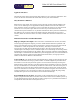
5.3 mm 50.8 mm 6.5 mm TOP VIEW 9.050 mm 8.500 mm 15.88 mm 9.000 mm 4.32 mm REAR VIEW L E E L E C T R O N I C E S O L U T I O N S X O L Copyright Elexol Pty Ltd 2008 Ether I/O 24 R Mechanicals 53.4 mm 30.6 mm 30.7 mm 2.7 mm 7.7 mm 3.2 mm 43.3 mm 3.6 mm (including through/hole components) PCB thickness = 1.6mm 63.5 mm 64.8 mm 9.282 mm 13.45 mm 9.65 mm 10.7 mm 20.0 mm 5.080 mm 2.577 mm 72 mm 72 mm 21.