POWER SUPPLY MODEL XP-15 Instruction Manual ELENCO Copyright © 2013 by Elenco® Electronics, Inc. All rights reserved. ® REV-A 753020 No part of this book shall be reproduced by any means; electronic, photocopying, or otherwise without written permission from the publisher.
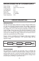
SPECIFICATIONS FOR XP-15 POWER SUPPLY Output Voltage Output Current Load Regulation Line Regulation Ripple Max. Short Protection Output Impedance 0 - 15VDC 0.3A @ 12V, 0.2A @ 15V 0.1V 0.1V 0.01V rms IC THERMO 0.3W CIRCUIT DESCRIPTION INTRODUCTION The XP-15 Power Supply features an output voltage variable from 0 to 15V at 0.3 ampere maximum current. The voltage is regulated to within 0.1V when going from no load to full load.
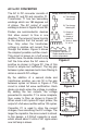
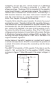
AC to DC CONVERTER The AC to DC converter consists of diodes D1 and D3 and capacitor C1. Transformer T1 has two secondary windings which are 180 degrees out of phase. The AC output of each winding is shown in Figure 2A and 2B. Voltage Waveform for Supply A) Transformer Winding AB B) Transformer Winding BC C) Output of Diodes are semiconductor devices diode D1. that allow current to flow in one D) Output of diode D3. direction.
In practice, the current through the diodes is not as shown in Figure 2E. Because capacitor C1 has a charge after the first cycle, the diode will not conduct until the positive AC voltage exceeds the positive voltage in the capacitor. Figure 5 shows a better picture of what the current flow looks like, assuming no loss in the diode. 20V Peak A) Transformer Winding 20V B) Voltage C1 C) Current through diodes Figure 5 It takes a few cycles for the voltage to build up on the capacitor.
Transistors Q1 and Q2 form a circuit known as a differential amplifier. Transistor Q1’s base is connected to a stable 1.5V reference voltage. The base of Q2 is connected to the regulator output circuit through a voltage divider network. The collector of transistor Q2 is connected to a current source. This basically is a PNP transistor biased to draw about 1mA current. Transistor Q2 sees the current source as a very high resistor of about 1 meg ohms. Thus, the gain of transistor Q2 is very high.
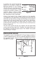
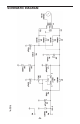
SCHEMATIC DIAGRAM REV-A -5-
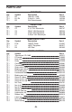
PARTS LIST RESISTORS Qty. r1 r2 r1 Symbol R2 R1, R4 R3 Description 150W 5% 1/4W 2.2kW 5% 1/4W 2kW Potentiometer Qty. r1 r1 r1 r1 Symbol C2 C4 C3 C1 Description 4.7mF 50V Electrolytic 220mF 16V Electrolytic 470mF 35V Electrolytic 2,200mF 35V Electrolytic Qty. r8 r1 r1 Symbol D1-8 U1 D9 Qty.
TWO YEAR WARRANTY All Elenco® models are guaranteed for two full years on all parts and service. For the first 3 months, your power supply is covered at absolutely no charge. For the remaining 21 months, a nominal service charge is required to cover shipping and handling. When returning merchandise for repair, please include proof of purchase, a brief letter of explanation of problem, and sufficient packing material.