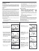
FUNCTION GENERATOR KIT MODEL FG-600K Assembly and Instruction Manual ELENCO ® Copyright © 2014, 1999 by ELENCO® All rights reserved. Revised 2014 REV-F No part of this book shall be reproduced by any means; electronic, photocopying, or otherwise without written permission from the publisher.
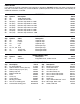
PARTS LIST If any parts are missing or damaged, see instructor or bookstore. DO NOT contact your place of purchase as they will not be able to help you. Contact ELENCO® (address/phone/e-mail is at the back of this manual) for additional assistance, if needed. RESISTORS Qty.
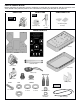
PARTS VERIFICATION Before beginning the assembly process, familiarize yourself with the components and this instruction book. Verify that all of the parts are present. This is best done by checking off the parts in the parts list.
INTRODUCTION Assembly of your FG-600 Function Generator will prove to be an exciting project and give much satisfication and personal achievement. The FG-600 contains a complete function generator capable of producing sine, square and triangle wave forms. The frequency of this generator can be contiuously varied from 1Hz to 1MHz in 6 steps. A fine frequency control makes selection of any frequency in between easy. The amplitude of the wave forms are adjustable from 0 to 3Vpp.
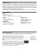
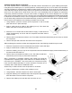
CONSTRUCTION Introduction • Turn off iron when not in use or reduce temperature setting when using a soldering station. The most important factor in assembling your FG-600 Function Generator Kit is good soldering techniques. Using the proper soldering iron is of prime importance. A small pencil type soldering iron of 25 watts is recommended. The tip of the iron must be kept clean at all times and well-tinned. • Tips should be cleaned frequently to remove oxidation before it becomes impossible to remove.
Assemble Surface Mount Components The most important factor in assembling your FG-600 Function Generator Kit is good soldering techniques. Using the proper soldering iron is of prime importance. A small pencil type iron of 10-15 watts is recommended. A sharply pointed tip is essential when soldering surface mount components. The tip of the iron should be kept clean and well tinned at all times. Many areas on the printed circuit board are close together and care must be given not to form solder shorts.
ASSEMBLE COMPONENTS TO THE PC BOARD Care must be given to identifying the proper components and in good soldering habits. Refer to the soldering tips section in this manual before you begin installing the components. Place a check mark in the box after each step is complete. R1 - 620Ω 5% 1/8W Res. Chip (621) C5 - .01µF Capacitor Chip (in the bag with lytic capacitors.) C7 - 10µF Electrolytic Chip (see Figure A) C4 - .1µF Capacitor Chip (in the bag with IC.) U1 - XR-2206P IC Surface Mnt.
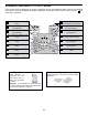
ASSEMBLE COMPONENTS TO THE PC BOARD R3 - 100kΩ Pot PC Mount R2 - 10kΩ Pot PC Mount (see Figure E) S1 - 6 position Rotary Switch (see Figure C) Jumper Wire Jumper Wire (see Figure G) C1 - 100µF 16V Electrolytic (see Figure D) C9 - 1000µF 16V Electrolytic (see Figure D) BT - Battery Snap (see Figure F) J1 - 3” Black Wire J2 - 3” Black Wire J3 - 3” Black Wire (see Figure H) S3 - Slide Switch S2 - Slide Switch Figure C Figure E Cut off tab Mount the pot down flush with the PC board.
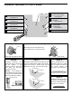
INSTALL COMPONENTS TO FRONT PANEL (continued) r Install the colored binding posts to the panel as shown in Figure I. Use the hardware shown in the figure. Make sure that the small nuts are tight. Nuts Lockwashers Small nut Binding post Black Figure I Yellow Yellow WIRING (See Figure J) r Solder the wire from hole J1 on the PC board to the first yellow binding post as shown. r Solder the wire from hole J2 on the PC board to the second yellow binding post as shown.
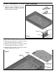
FINAL ASSEMBLY r Fit the PC board assembly into the top case, making sure that all switches and pots come through the holes in the panel as shown in Figure K. 7mm Hex pot nuts 9mm Hex switch nut r Place the washers onto their locations as shown in Figure K, being careful to check the sizes. Then, tighten the hex nuts onto the potentiometers and rotary switch, noting their size as shown in Figure K.
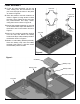
FINAL ASSEMBLY (continued) r Remove the backing from each rubber foot and place them in the locations shown in Figure M. r Turn the shafts on the two potentiometers and rotary switch fully counter-clockwise. Push the three knobs onto the shafts so that the line on the knobs are on the points shown in Figure N. r Assemble the top and bottom case sections and fasten with four 2.8 x 8mm self-tapping screws as shown in Figure M. Make sure the slots on the side line up with one another. 2.
TESTING THE FG-600 FUNCTION GENERATOR The unit may be tested by following the 4 steps listed below. Should any of these tests fail, refer to the Troubleshooting Guide below. 1) SET THE SWITCHES AND POTS AS FOLLOWS: On/Off Range Frequency Amplitude Sine/Triangle 3) FREQUENCY CONTROLS 6 range settings, vary the FREQUENCY pot from max to min and check that the frequency varies according to Table 1 on page 13.
FUNCTIONAL DESCRIPTION The FG-600 is a function generator integrated circuit capable of producing high quality sine, triangle, and square waves of high stability and accuracy. A picture of each waveform is shown below: Sine Wave Triangle Wave Square Wave THEORY OF OPERATION The heart of the FG-600 Function Generator is the XR-2206 monolithic function generator integrated circuit. The XR-2206 is comprised of four main functional blocks as shown in the functional block diagram (Figure 1).
CONTROLS RANGE SWITCHES Six ranges of frequency are provided by the range switch as shown in Table 1. POSITION 1 2 3 4 5 6 TYPICAL FREQUENCY RANGE 1Hz - 15Hz 10Hz - 150Hz 100Hz - 1.5kHz 1kHz - 15kHz 10kHz - 150kHz 100kHz - 1MHz Table 1 SINE/TRIANGLE SWITCH ON/OFF SWITCH This SINE/TRIANGLE Switch selects the waveform, sine wave or triangle wave, sent to the SINE/TRIANGLE output terminal. The ON/OFF Switch turns the power to the FG-600 on or off.
EDUCATION KITS Complete with PC Board and Instruction Book Space War Gun 0-15V Power Supply Christmas Tree K-10 K-11 K-14 Rapid fire or single shot with 2 A low-cost way to supply Produces flashing flashing LEDs. voltage to electronic games, colored LEDs etc. and three popular Christmas melodies. Requires 9V battery Requires 9V battery 0-15VDC @ 300mA LED Robot Blinker K-17 You’ll have fun displaying the PC board robot. Learn about free-running oscillators.
150 Carpenter Avenue l Wheeling, IL 60090 (847) 541-3800 l www.elenco.com l e-mail: elenco@elenco.com ELENCO ® Answers: 1) XR-2206; 2) A Voltage Controlled Oscillator, An Analog Multiplier and Sine Shaper, Unity Gain Buffer Amplifier and A Set of Current Switches; 3) Current; 4) Frequency; 5) 1/RC; 6) RC; 7) output; 8) triangle; 9) sine; 10) 1Hz to 15Hz, 10Hz to 150Hz, 100Hz to 1.5kHz, 1kHz - 15kHz, 10kHz - 150kHz, 100kHz - 1MHz.