POWER SUPPLY KIT MODEL XP-720K Assembly Manual ELENCO Copyright © 2012, 1998 by ELENCO® All rights reserved. ® Revised 2012 REV-G No part of this book shall be reproduced by any means; electronic, photocopying, or otherwise without written permission from the publisher.
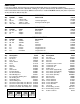
PARTS LIST If you are a student, and any parts are missing or damaged, please see instructor or bookstore. If you purchased this kit from a distributor, catalog, etc., please contact Elenco® Electronics (address/phone/email is at the back of this manual) for additional assistance, if needed. DO NOT contact your place of purchase as they will not be able to help you. RESISTORS Qty. Symbol Value r r r r R5 R3, R4 R1, R2 VR1, VR2 .18Ω 5% 3W 2.7Ω 5% 1/4W 150Ω 5% 1/4W 2kΩ Potentiometer Qty.
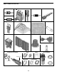
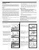
PARTS IDENTIFICATION Resistor 2kΩ Potentiometer Capacitor Diode Transistor .
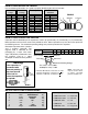
IDENTIFYING RESISTOR VALUES Use the following information as a guide in properly identifying the value of resistors. BAND 1 1st Digit Color Black Brown Red Orange Yellow Green Blue Violet Gray White BAND 2 2nd Digit Digit 0 1 2 3 4 5 6 7 8 9 Color Black Brown Red Orange Yellow Green Blue Violet Gray White Multiplier Digit 0 1 2 3 4 5 6 7 8 9 Color Black Brown Red Orange Yellow Green Blue Silver Gold Resistance Tolerance Multiplier 1 10 100 1,000 10,000 100,000 1,000,000 0.01 0.
CONSTRUCTION Introduction • Turn off iron when not in use or reduce temperature setting when using a soldering station. The most important factor in assembling your XP-720K Power Supply Kit is good soldering techniques. Using the proper soldering iron is of prime importance. A small pencil type soldering iron of 25 - 40 watts is recommended. The tip of the iron must be kept clean at all times and well tinned. • Tips should be cleaned frequently to remove oxidation before it becomes impossible to remove.
ASSEMBLE COMPONENTS TO PC BOARD Figure A Band Diodes have polarity. Be sure that the band is in the correct direction. Figure B Electrolytics have a polarity marking indicating the (–) lead. The PC board is marked to show the lead position. Figure C Flat Polarity Mark (–) (+) Warning: If the capacitor is connected with incorrect polarity it may heat up and either leak or cause the capacitor to explode.
PC BOARD WIRING Cut the 22 gauge wires to the required length. Strip 1/4” of insulation off of both ends. Insert the lead into the hole and solder it to the foil side.
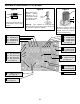
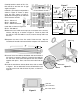
PANEL ASSEMBLY r Install binding posts 1-7 with the colors in order, as shown in Figure D. Insert the post into the hole and fasten it with the nut and lockwasher. Tighten down the nut with pliers. r Turn both potentiometer shafts all the way counter-clockwise. Line up the line on the knobs with the first line on the voltage scale. Press knobs onto the shaft of the potentiometers. R EA S E NC I r Cut off the tabs on the two potentiometers and install them with the lugs up, as shown in Figure D.
Carefully bend the leads of IC1, IC2, IC3 and Q2 on the heat sink at right angles with pliers. Heatsink Install IC1, IC2 and Q2 in the positions shown in Figure E. Fasten in place using the parts shown in Figure F. Spread the silicon grease on the back of the transistor and ICs.
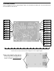
WIRING LINE CORD, FUSE, TRANSFORMER AND SWITCH r Install the line cord ground lug to the chassis using a 6-32 x 3/8” screw and a 6-32 large nut in the location shown in Figure I. 1/2” Tubing Side Lug End Lug r Strip the insulation off of both ends of the 6” red 20 ga. wire to expose 1/4” of bare wire. Solder one end of the wire to lug 3 on the rocker switch, as shown in Figure I. Ribbed Line Cord U V W T1 CT1 T1 6-32 Large Nut Red Red Blue Yellow Black (B) Black Yellow Blue 6” 20 Ga.
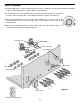
WIRE BINDING POSTS AND 317, 337 Solder the wires from the board to the binding posts, as shown in Figure K. r 3” Orange wire from (G) on the PC board; To the Yellow post (-1.25-15V). r 4” Blue wire from (H) on the PC board and the 6” blue wire from the black AC binding post; To the Black post (common). r 3” Red wire from (I) on the PC board; To the Red post (+1.25-15V). r 4” Red wire from (C) on the PC board; To the Red post (+5V 3A).
WIRE 2N6124, 7805 & POTENTIOMETERS Insert the wires from the PC board through the rectangular hole in the chassis to the 2N6124 and LM-7805, solder into place, as shown in Figure L. 7805 2N6124 r 5” Red wire (L) from the PC board; To middle lead 0f 2N6124. r 5” Orange wire (P) from the PC board; To left lead of 2N6124. r 5” Blue wire (N) from the PC board; To right lead of 2N6124. r 4 1/2” Red wire (O) from PC board; To middle lead of LM-7805. r 4 1/2” Blue wire (Q) from PC board; To left lead of LM-7805.
FINAL ASSEMBLY r Fasten the heat sink to the chassis with two 6 x 3/8” black pan head screws, as shown in Figure M. r Fit the cover onto the chassis. Fasten in place with two 6 x 3/8” black truss head screws on each side, as shown in Figure M.
TESTING THE XP-720 POWER SUPPLY Testing the XP-720 Power Supply is very simple. Before applying power to the unit, be sure that all wiring and soldering is firm. If so, obtain a digital voltmeter. 1. Apply power to the XP-720 and measure the output voltages. Output Voltages: Positive Variable DC 1.25 - 15V Negative Variable DC –1.25 - –15V +5VDC 4.75 - 5.25 12.6VAC 11 - 14 2. Short the output of each of the DC outputs to ground one at a time. ONLY SHORT THE DC OUTPUTS.
CIRCUIT DESCRIPTION Introduction The Model XP-720 Power Supply features three solid-state DC power supplies and a 12.6VAC center tapped output. The first two supplies consist of one positive and one negative 1.25 to 15 volts at 1 ampere. The third has a fixed 5V at 3 amperes. All DC supplies are fully regulated. A special IC circuit keeps the output voltage within .2V when going from no load to full load. The output is fully protected from short circuits.
In practice, the current through the diodes is not as shown in Figure 2C. Because capacitor C5 has a charge after the first cycle, the diode will not conduct until the positive AC voltage exceeds the positive charge in the capacitor. Figure 5 shows a better picture of what the current flow looks like, assuming no loss in the diode. It takes a few cycles for the voltage to build up on the capacitor. This depends on the resistance of the winding and diode.
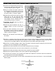
The LM-317 IC is basically a 1.25V regulator. To be able to vary the output 1.25 - 15V, we stack the IC on a DC voltage as shown in Figure 6A. When VR1 equals 0, the output voltage is 1.25V as determined by the LM-317 IC. Note that the voltage across R1 is always 1.25V. When R1 equals VR1, the voltage across VR1 will equal the two volts across R1, therefore, the output voltage will be 2.5V. When VR1 is 5 times R1, the output voltage is 7.5V. As you can see, varying resistor VR1 will vary the voltage from 1.
QUIZ 1. AC voltage is supplied to the rectifier stages by the . . . r A. step up transformer. r B. step down transformer. r C. 1 to 1 transformer. r D. AC to DC transformer. 2. The secondary windings of the transformer are . . . r A. 90O out of phase. r B. 180O out of phase. r C. 270O out of phase. r D. 320O out of phase. 3. Diodes allow current to flow . . . r A. when the anode is more negative than the cathode. r B. when the cathode is more positive than the anode. r C. in one direction. r D.
SPECIFICATIONS ON XP-720 POWER SUPPLY Input Voltage Current Protection 110-130VAC 1A Output Voltage (at 120V input) 1) 2) 3) 4) 1.25-15VDC @ 1A –1.25 - –15VDC @ 1A 5VDC @ 3A 6.3, 12.6CTAC @ 1A Output Regulation 200mV each supply Line Regulation 100mV each supply Ripple Max 5mV rms Current Protection Thermal overload ±15VDC Current limiting 5VDC Fuse 6.3VAC Short Protection Current limiting 5VDC, ±15VDC Fuse 6.3VAC Output Impedance .2Ω ±15VDC .06Ω 5VDC Maximum output individually rated.
Elenco® Electronics, Inc. 150 Carpenter Avenue Wheeling, IL 60090 (847) 541-3800 Website: www.elenco.com e-mail: elenco@elenco.