
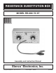
User guide

-6-
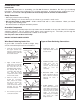
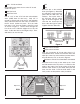
Installation of Knobs without an Ohm Meter
If an ohm meter is not available, turn both switches
so that the wiper contact is in the position shown in
Figure 5. Start with switch SW1, follow the copper
run on the PC board from the lug in contact with the
wiper to the 470W (R7) resistor, to be sure that the
switch is set in the proper position. Align the knob
on the SW1 (W) switch to the 470 position, push the
knob onto the shaft. Follow the same procedure for
switch SW2 (KW), except follow the copper run to
the 6.8KW (R13) resistor. Align the knob on the
SW2 (KW) switch to the 6.8 position.
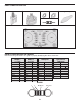
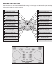
TESTING THE CIRCUIT
SCHEMATIC DIAGRAM
SW1
W
W
POSITION
Value Position Meter Reading
10W
22W
47W
100W
220W
330W
470W
680W
1000W
2200W
3300W
4700W
SW2 K
W
W
POSITION
Value Position Meter Reading
6.8KW
10KW
22KW
33KW
47KW
68KW
100KW
220KW
330KW
470KW
680KW
1MW
Figure 5
Wiper Contact
LugPC Board
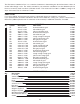
The following test is to be made with your meter to determine that the resistors are in their correct circuit
positions. The resistors used in your circuit are gold banded with a tolerance of +5%. That means that a 10kW
resistor could measure between 9,500W and 10,500W and be correct. Each of the 24 resistance value positions
will be tested and recorded in the chart below.