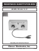
RESISTANCE SUBSTITUTION BOX MODEL RS-400 / K-37 Assembly and Instruction Manual Elenco Electronics, Inc. TM TM Copyright © 1990 Elenco Electronics, Inc.
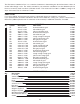
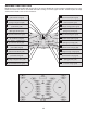
The Resistance Substitution Box is a convenient instrument in determining the desired resistance values in circuits under design or test. The values selected for your resistance substitution box were determined to be the most commonly used in modern solid-state circuits. The values are from 10W to 1,000kW (1 meg) in 24 steps. All resistors are 5% tolerance 1/2 watt. PARTS LIST If you are a student, and any parts are missing or damaged, please see instructor or bookstore.
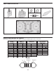
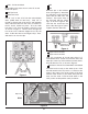
PARTS IDENTIFICATION 9mm Nut Switch 12 Position Switch PC Mount Washer Alligator Clip Resistor PC Board IDENTIFYING RESISTOR VALUES Use the following information as a guide in properly identifying the value of resistors.
CONSTRUCTION Introduction The most important factor in assembling your RS-400 Resistance Substitution Box Kit is good soldering techniques. Using the proper soldering iron is of prime importance. A small pencil type soldering iron of 25 40 watts is recommended. The tip of the iron must be kept clean at all times and well tinned. Safety Procedures • Wear eye protection when soldering. • Locate soldering iron in an area where you do not have to go around it or reach over it.
ASSEMBLY INSTRUCTIONS Begin the PC board assembly with resistor R12. Be sure to identify the correct value by reading the color code. Place the resistor into the PC board with the leads coming out on the copper foil side. Solder in place and clip off the excess leads, close to the connection. R12 - 4.7kW 5% 1/2W Resistor (yellow-violet-red-gold) R19 - 100kW 5% 1/2W Resistor (brown-black-yellow-gold) R11 - 3.
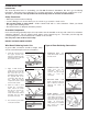
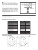
SW3 - PC Mount Switch SW1 Mount SW3 in the place shown on the PC board. Solder into place. SW2 Bend the tab on the switches down (see Figure 2). Attach the two switches loosely to the front panel with the 9mm nuts and washers. Line up the holes of the PC board with the switch lugs, as shown in Figure 3. Be sure that the board lays flat, then solder the lugs into place. Tighten down the 9mm nuts.
Installation of Knobs without an Ohm Meter PC Board If an ohm meter is not available, turn both switches so that the wiper contact is in the position shown in Figure 5. Start with switch SW1, follow the copper run on the PC board from the lug in contact with the wiper to the 470W (R7) resistor, to be sure that the switch is set in the proper position. Align the knob on the SW1 (W) switch to the 470 position, push the knob onto the shaft.
ElencoTM Electronics, Inc. 150 W. Carpenter Avenue Wheeling, IL 60090 (847) 541-3800 http://www.elenco.com e-mail: elenco@elenco.