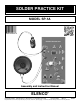
SOLDER PRACTICE KIT MODEL SP-1A Assembly and Instruction Manual ELENCO Copyright © 2012, 1994 by Elenco® Electronics, Inc. All rights reserved. ® Revised 2012 REV-T No part of this book shall be reproduced by any means; electronic, photocopying, or otherwise without written permission from the publisher.
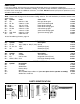
PARTS LIST If you are a student, and any parts are missing or damaged, please see instructor or bookstore. If you purchased this kit from a distributor, catalog, etc., please contact ELENCO® (address/phone/e-mail is at the back of this manual) for additional assistance, if needed. DO NOT contact your place of purchase as they will not be able to help you. RESISTORS Note: Please refer to page 3 for the resistor reading exercise. This will familiarize you with the resistor color band coding. Qty.
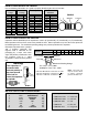
IDENTIFYING RESISTOR VALUES Use the following information as a guide in properly identifying the value of resistors. BAND 1 1st Digit Color Black Brown Red Orange Yellow Green Blue Violet Gray White BAND 2 2nd Digit Digit 0 1 2 3 4 5 6 7 8 9 Color Black Brown Red Orange Yellow Green Blue Violet Gray White Multiplier Digit 0 1 2 3 4 5 6 7 8 9 Color Black Brown Red Orange Yellow Green Blue Silver Gold Resistance Tolerance Multiplier 1 10 100 1,000 10,000 100,000 1,000,000 0.01 0.
RESISTOR READING EXERCISE Before starting assembly of your solder practice project, you should be thoroughly familiar with the 4-band color code system. Many of the resistor values will be identified by color bands and it is easy to mistake their value if you read the colors incorrectly or read the value from the wrong end. Do the following exercise in resistor values. Place your answer in the box beneath the resistor. Answers are on the bottom of this page.
INTRODUCTION quickly than the iron would either by itself or when used with leaded solder. Almost every electronic device today has a printed circuit board. Whether you are assembling a PC board or repairing it, you must understand the basics of working with these boards. When using lead-free solders it is very important that tips are properly maintained, otherwise tip life will be reduced significantly. Tips should be cleaned frequently to remove oxidation before it becomes impossible to remove.
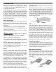
Types of Soldering Devices Tip Cleaning A number of different types of soldering devices: irons, guns and stations are available today. Irons are used for light to medium work and guns are for medium to heavy-duty work. The station type can range from light to heavy-duty For working on PC boards, irons ranging from 15 to 40 watts are suitable, or a station with a range of 15 to 40 watts. If you use an iron with a higher wattage rating than 40 watt, you may damage the copper tracks on the PC board.
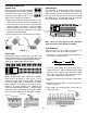
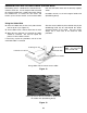
SOLDER PRACTICE Double Pads Solder Resist Before we begin to assemble and solder the components to the solder practice PC board, we will start first by practice soldering to the double pads on the Figure 3 edge of the PC board (see Figure 3). The PC board is covered with solder resist over areas that are not to be soldered. This is done to reduce soldering shorts to adjacent metal runs. On the large pad, note that half of the pad is covered with solder resist. Try soldering to the covered pad.
PC BOARD REPAIR Hairline Cracks Wide Gaps The hairline cracks can develop in the copper foil if the PC board is flexed. This can be easily repaired by making a solder bridge across the two foils. The solder should smoothly flow across the foil as shown in Figure 8. If the solder does not adhere to the foil, it will sit on the foil as a blob as shown in Figure 9. For wider gaps in a copper foil, a solder bridge can not be used. A small wire would be used to bridge the copper as shown in Figure 11.
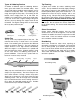
REMOVING EXCESS SOLDER USING SOLDER WICK Desoldering wick is a braided wire coated with noncorrosive rosin flux. It is the simplest and safest tool for removing solder from a solder connection. When the braided wire is heated, the flux cleans and breaks up the surface tension so the melted solder from the connection flows into the braid by capillary action. Included in this kit is a six inch length of solder wick (desoldering braid).
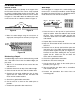
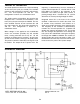
THEORY OF OPERATION The solder practice kit consists of a circuit oscillating at one hertz (one cycle per second). The oscillator consists of two transistors Q1 and Q2, and resistors, R1 - R11 and capacitors C1 and C2. This configuration is known as a multivibrator circuit. frequency is determined by the time constants of resistor R6 and capacitor C1, also R4 and C2. Two LED diodes are placed in the collectors of the transistors. The LED's will light when current is passing through them.
CONSTRUCTION Introduction • Turn off iron when not in use or reduce temperature setting when using a soldering station. The most important factor in assembling your SP-1A / AK-100 Solder Practice Kit is good soldering techniques. Using the proper soldering iron is of prime importance. A small pencil type soldering iron of 25 - 40 watts is recommended. The tip of the iron must be kept clean at all times and well tinned.
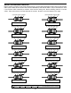
PC BOARD ASSEMBLY NOTE: Before beginning assembly, please refer to page 13 for the resistor reading exercise. This will familiarize you with the resistor color band coding. Solder the following parts to the PC board. R9 - 10kΩ 5% ¼W Resistor (brown-black-orange-gold) (see Figure E) Battery Snap (see Figure A) R8 - 10kΩ 5% ¼W Resistor (brown-black-orange-gold) (see Figure E) C5 - .02μF or .
PC BOARD ASSEMBLY (continued) Solder the following parts to the PC board. R5 - 47kΩ 5% ¼W Resistor (yellow-violet-orange-gold) (see Figure E) R3 - 68Ω 5% ¼W Resistor (blue-gray-black-gold) (see Figure E) R4 - 22kΩ 5% ¼W Resistor (red-red-orange-gold) (see Figure E) R2 - 1kΩ 5% ½W Resistor (brown-black-red-gold) (see Figure E) C4 - .02μF or .
OPERATION After completing the assembly of the kit, double back to see that the soldering looks good and all of the components are in their proper place. If everything is all right, attach the 9V battery to the battery snap. The LED’s should alternately light and the speaker should sound a wobbling siren. Continue to the Desoldering Practice/Component Replacement Section. Note: Refer to the Troubleshooting Section if your circuit does not work.
WORD GLOSSARY Capacitor An electrical component that can store electrical pressure (voltage) for periods of time. Resistor Component used to control the flow of electricity in a circuit. It is made of carbon. Cold Solder Joint Occurs because insufficient heat was applied or the connection was moved before the solder had set. Connection looks crystalline, crumbly, or dull. Rosin Core Solder The most common type of solder used in electronics generally referred to as 63/37 rosin core solder.
QUIZ 1. The oscillator in this kit is known as a . . . r A. one-shot circuit. r B. multivibrator circuit. r C. three phase circuit. r D. tri-state circuit. 6. Solder wick is used to . . . r A. remove solder. r B. solder in small parts. r C. cleaning the soldering iron tip. r D. removing flux. 2. What type of flux should be used in electronics? r A. Chloride r B. Organic r C. Rosin r D. Corrosive 7. A cold solder joint is caused by . . . r A. a solder bridge. r B. using 60/40 solder. r C.