
Instruction Manual
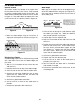
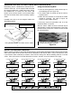
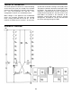
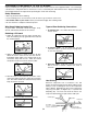
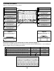
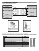
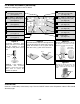
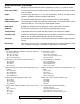

Figure G
Mount the LED onto the PC board with
the flat side of the LED in the same
direction as marked on the PC board.
Figure H
Mount the IC with the flat side in the
same direction as marked on the PC
board. Solder and cut off the excess
leads.
R6 - 56kΩ 5% ¼W Resistor
(green-blue-orange-gold)
(see Figure B)
R5 - 330Ω 5% ¼W Resistor
(orange-orange-brown-gold)
(see Figure B)
C1 - 10μF 16V Electrolytic
(see Figure E)
Battery Snap (see Figure F)
SW1 - Switch SPST
LED1 - Red LED
(see Figure G)
Q1 - 2N3904 Transistor
(see Figure H)
R12 - 56kΩ 5% ¼W Resistor
(green-blue-orange-gold)
(see Figure B)
R11 - 330Ω 5% ¼W Resistor
(orange-orange-brown-gold)
(see Figure B)
C2 - 10μF 16V Electrolytic
(see Figure E)
LED2 - Red LED
(see Figure G)
Q2 - 2N3904 Transistor
(see Figure H)
J7 - Jumper Wire
(see Figure A)
PC BOARD ASSEMBLY (continued)
Solder the following parts to the PC board.
-12-
Figure E
Electrolytic capacitors have
polarity. Be sure to mount them
with the negative (–) lead
(marked on side) in the correct
hole.
Warning: If the capacitor is
connected with incorrect
polarity, it may heat up and
either leak or cause the
capacitor to explode.
Figure F
Thread the battery snap wires through the hole
in the PC board from the solder side as shown.
Solder the red wire to the (+) point and the
black wire to the (–) point on the PC board.
Black
Red
OPERATION
Connect a 9 volt battery to the battery snap. Turn the ON/OFF switch to the ON position and the LEDs should
alternately light.
Flat
(–) (+)
Polarity
Mark
Mount flush
with PC board
Flat