
Instruction Manual

1
8
9
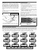
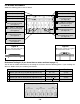
U1 - 16-pin IC Socket
(see Figure C)
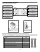
R14 - 27kΩ 5% ¼W Resistor
(red-violet-orange-gold)
(see Figure D)
R13 - 18kΩ 5% ¼W Resistor
(brown-gray-orange-gold)
(see Figure D)
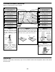
R17 - 100kΩ 5% ¼W Resistor
(brown-black-yellow-gold)
(see Figure D)
R18 - 120kΩ 5% ¼W Resistor
(brown-red-yellow-gold)
(see Figure D)
R15 - 39kΩ 5% ¼W Resistor
(orange-white-orange-gold)
(see Figure D)
R16 - 47kΩ 5% ¼W Resistor
(yellow-violet-orange-gold)
(see Figure D)
R19 - 470kΩ 5% ¼W Resistor
(yellow-violet-yellow-gold)
(see Figure D)
R20 - 680kΩ 5% ¼W Resistor
(blue-gray-yellow-gold)
(see Figure D)
PC BOARD ASSEMBLY (continued)
Solder the following parts to the PC board.
-11-
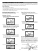
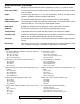
Figure D
Stand resistor on end as
shown with the body
inside the white circle
White Circle
Figure C
When mounting the IC socket,
make sure that the notch is in the
same direction as marked on the
PC board.
Notch
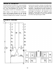
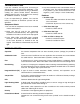
Resistance Testing #2 (If you do not have a meter, continue to page 12)
Each resistor is connected across two pins of the IC socket. You will test the solder connections by measuring
the resistance from the following IC pins. If your readings are different, double check your soldering connections.
Location Value
R14 - Measure from pin 1 to pin 2 27kΩ +/– 5%
R13 - Measure from pin 3 to pin 4 18kΩ +/– 5%
R17 - Measure from pin 5 to pin 6 100kΩ +/– 5%
R18 - Measure from pin 7 to pin 8 120kΩ +/– 5%
R19 - Measure from pin 9 to pin 10 470kΩ +/– 5%
R20 - Measure from pin 11 to pin 12 680kΩ +/– 5%
R16 - Measure from pin 13 to pin 14 47kΩ +/– 5%
R15 - Measure from pin 15 to pin 16 39kΩ +/– 5%
16