
Instruction Manual
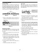

PC BOARD ASSEMBLY
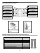
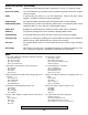
Solder the following parts to the PC board.
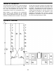
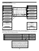
Resistance Testing #1 (If you do not have a meter, continue to page 11)
You will test the solder connections by measuring the resistance from the following points. If your readings are
different, double check your soldering connections.
Location Value Circuit
Point A (left side of J1) to point B (right side of J3) 0.1 - 1Ω (J1-J3)
Point A (left side of J1) to point C (top lead of R4) 670Ω
+
5% (J1-J3, R1-R4)
Point D (left side of J4) to point E (right side of J6) 0.1 - 1Ω
+
5% (J4-J6)
Point D (left side of J4) to point F (top lead of R10) 670Ω
+
5% (J4-J6, R7-R10)
J2 - Jumper Wire (see Fig. A)
J1 - Jumper Wire (see Fig. A)
J5 - Jumper Wire (see Fig. A)
J4 - Jumper Wire (see Fig. A)
R1 - 100Ω 5% ¼W Resistor
(brown-black-brown-gold)
(see Figure B)
R2 - 150Ω 5% ¼W Resistor
(brown-green-brown-gold)
(see Figure B)
R3 - 200Ω 5% ¼W Resistor
(red-black-brown-gold)
(see Figure B)
R4 - 220Ω 5% ¼W Resistor
(red-red-brown-gold)
(see Figure B)
J3 - Jumper Wire (see Fig. A)
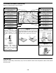
J6 - Jumper Wire (see Fig. A)
R10 - 220Ω 5% ¼W Resistor
(red-red-brown-gold)
(see Figure B)
R9 - 200Ω 5% ¼W Resistor
(red-black-brown-gold)
(see Figure B)
R8 - 150Ω 5% ¼W Resistor
(brown-green-brown-gold)
(see Figure B)
R7 - 100Ω 5% ¼W Resistor
(brown-black-brown-gold)
(see Figure B)
-10-
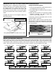
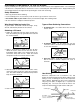
Figure A
Cut a 1” wire and strip 1/8” of
insulation off of both ends.
Figure B
Mount the resistor flat against
the PC board as shown.
A
D
CF
E
B