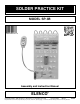
SOLDER PRACTICE KIT MODEL SP-3B Assembly and Instruction Manual ELENCO Copyright © 2012, 2001 by Elenco® Electronics, Inc. All rights reserved. ® Revised 2012 REV-K No part of this book shall be reproduced by any means; electronic, photocopying, or otherwise without written permission from the publisher.
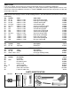
PARTS LIST If you are a student, and any parts are missing or damaged, please see instructor or bookstore. If you purchased this kit from a distributor, catalog, etc., please contact Elenco® (address/phone/e-mail is at the back of this manual) for additional assistance, if needed. DO NOT contact your place of purchase as they will not be able to help you. RESISTORS Note: Please refer to page 7 for the resistor reading exercise. This will familiarize you with the resistor color band coding. Qty.
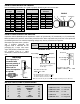
IDENTIFYING RESISTOR VALUES Use the following information as a guide in properly identifying the value of resistors. BAND 1 1st Digit Color Black Brown Red Orange Yellow Green Blue Violet Gray White BAND 2 2nd Digit Digit 0 1 2 3 4 5 6 7 8 9 Color Black Brown Red Orange Yellow Green Blue Violet Gray White Multiplier Digit 0 1 2 3 4 5 6 7 8 9 Color Black Brown Red Orange Yellow Green Blue Silver Gold Resistance Tolerance Multiplier 1 10 100 1,000 10,000 100,000 1,000,000 0.01 0.
CONSTRUCTION Introduction Safety Procedures The most important factor in assembling your SP-3B Solder Practice Kit is good soldering techniques. Using the proper soldering iron is of prime importance. A small pencil type soldering iron of 25 40 watts is recommended. The tip of the iron must be kept clean at all times and well tinned. • Always wear safety glasses or safety goggles to protect your eyes when working with tools or soldering iron, and during all phases of testing.
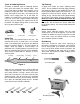
Types of Soldering Devices Tip Cleaning A number of different types of soldering devices: irons, guns and stations are available today. Irons are used for light to medium work and guns are for medium to heavy-duty work. The station type can range from light to heavy-duty For working on PC boards, irons ranging from 15 to 40 watts are suitable, or a station with a range of 15 to 40 watts. If you use an iron with a higher wattage rating than 40 watt, you may damage the copper tracks on the PC board.
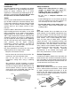
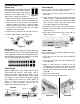
SOLDER PRACTICE Double Pads Tack Soldering Before we begin to assemble and solder the components to the solder practice PC board, we will start first by practice soldering to the double pads on the Figure 4 edge of the PC board (see Figure 4). You will make 10 tack solder connections by soldering five wires to the top row of pads. 1. Cut 5 one-inch wires and strip 1/8” insulation off both ends. 2. Place the iron and the wire on top left pad as shown in Figure 7. Allow the solder to flow around the wire.
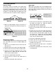
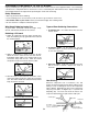
PC BOARD REPAIR Hairline Cracks Wide Gaps The hairline cracks can develop in the copper foil if the PC board is flexed. This can be easily repaired by making a solder bridge across the two foils. The solder should smoothly flow across the foil as shown in Figure 9. If the solder does not adhere to the foil, it will sit on the foil as a blob as shown if Figure 10. Wide gaps in the copper foil can be bridged using a small wire soldered across the gaps (see Figure 12).
REMOVING EXCESS SOLDER USING DESOLDERING WICK Using the Desoldering Wick Desoldering wick is a braided wire coated with noncorrosive rosin flux. It is the simplest and safest tool for removing solder from a solder connection. When the braided wire is heated, the flux cleans and breaks up the surface tension so the melted solder from the connection flows into the braid by capillary action. 1. Place the wick against the solder with the tip of a hot soldering iron (see Figure 13). 2.
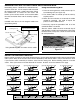
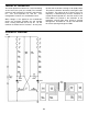
THEORY OF OPERATION The solder practice kit consists of a circuit oscillating at one hertz (one cycle per second). The oscillator consists of two transistors Q1 and Q2, and resistors, R1 - R11 and capacitors C1 and C2. This configuration is known as a multivibrator circuit. Q2 will start to conduct, causing Q1 to rapidly cutoff. This process continues alternately causing Q1 or Q2 to conduct. The output will be a square wave.
SOLDERING COMPONENTS TO THE PC BOARD A poorly soldered joint can greatly affect small current flow in circuits and can cause equipment failure. You can damage a PC board or a component with too much heat or cause a cold solder joint with insufficient heat. Sloppy soldering can cause bridges between two adjacent foils preventing the circuit from functioning. Safety Procedures • • • • Wear eye protection when soldering. Locate soldering iron in an area where you do not have to go around it or reach over it.
PC BOARD ASSEMBLY Solder the following parts to the PC board. J2 - Jumper Wire (see Fig. A) J3 - Jumper Wire (see Fig. A) J1 - Jumper Wire (see Fig. A) J6 - Jumper Wire (see Fig. A) J5 - Jumper Wire (see Fig. A) J4 - Jumper Wire (see Fig.
PC BOARD ASSEMBLY (continued) Solder the following parts to the PC board.
PC BOARD ASSEMBLY (continued) Solder the following parts to the PC board.
TROUBLESHOOTING 4. Pay close attention to the red and black wires of the battery snap. The red wire should be installed in the positive (+) hole and the black wire in the negative (–) hole. Snap in a fresh 9-volt battery. If you are a student, and any parts are missing or damaged, please see instructor or bookstore. If you purchased this solder practice kit from a distributor, catalog, etc.
WORD GLOSSARY (continued) Resistor Component used to control the flow of electricity in a circuit. It is made of carbon. Rosin Core Solder The most common type of solder used in electronics generally referred to as 63/37 rosin core solder. Solder A tin/lead alloy that melts at a very low temperature, used to join other metals together. It produces excellent electrical connections. Solder Bridge An unwanted solder connection between two points that are close together.
ELENCO® 150 Carpenter Avenue Wheeling, IL 60090 (847) 541-3800 Website: www.elenco.com e-mail: elenco@elenco.