® MICRO - MASTER MM-8000 8085 MICROPROCESSOR - BASIC SYSTEMS COURSE COMPUTER THEORY - CONSTRUCTION AND PROGRAMMING Copyright © 2008, 1989 by Elenco® Electronics, Inc. All rights reserved. Revised 2008 REV-D No part of this book shall be reproduced by any means; electronic, photocopying, or otherwise without written permission from the publisher.
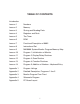
TABLE OF CONTENTS Introduction Lesson 1 Numbers Lesson 2 Memory Lesson 3 Storing and Reading Data Lesson 4 Registers and Parts Lesson 5 The Timer Lesson 6 ROM Lesson 7 Functional Description of 8085 Lesson 8 Instructional Set Lesson 9 MM-8000 System-Monitor Program-Memory Map Lesson 10 Program 1; Initialization of Monitor Lesson 11 Program 2; Display/Delay Routines Lesson 12 Program 3; Scan Routine Lesson 13 Program 4; Function Routines Lesson 14 Program 5; Addition of Number - Ke
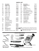
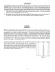
PARTS LIST Qty Description Part # 9 1 1 3 1 8 3 14 8 14 5 2 RESISTORS 150Ω 5% 1/4W 470Ω 5% 1/4W 510Ω 5% 1/4W 680Ω 5% 1/4W 1kΩ 5% 1/4W 1.2kΩ 5% 1/4W 2kΩ 5% 1/4W 3.9kΩ 5% 1/4W 6.8kΩ 5% 1/4W 10kΩ 5% 1/4W 47kΩ 5% 1/4W 68kΩ 5% 1/4W 131500 134700 135100 136800 141000 141200 142000 143900 146800 151000 154700 156800 1 1 10 1 2 CAPACITORS 20pF Discap 330pF Discap 0.
III
IV
V
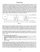
CONSTRUCTION Introduction The most important factor in assembling your MM-8000 Micro-Master® Kit is good soldering techniques. Using the proper soldering iron is of prime importance. A small pencil type soldering iron of 25 - 40 watts is recommended. The tip of the iron must be kept clean at all times and well tinned. Safety Procedures • • • • Wear eye protection when soldering and during all phases of construction. Locate soldering iron in an area where you do not have to go around it or reach over it.
VII
1-1
1-2
2-1
(may be marked C1 on the PC board) 2-2
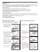
* * Warning: If the capacitor is connected with incorrect polarity, it may heat up and either leak or cause the capacitor to explode. Clip on heat sink and install at a 45O angle as shown.
2-4
2-5
2-6
3-1
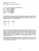
3.9kΩ Resistor R43 R2 2N3904 Transistor Q3 680Ω Resistor R69 10kΩ Resistor R14 47kΩ Resistor R8 68kΩ Resistor R10 2kΩ Resistor R12 R9 C11 680Ω Resistor R6 330pF Discap (330) C15 10kΩ Resistor R45 SPDT Switch SW4 SW6 3.9kΩ Resistor R13 Before installing, cut off ears Figure 3-1 3-2 Jumper J10 Use a discarded resistor lead.
3-3
3-4
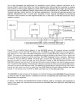
This switch connected to the 8155 integrated circuit chip enable (CE) pin through transistor Q3. When the switch is down (toward the edge of the board) the transistor is turned off. The CE pin is held high by resistor R69. In this state the 8155 is disabled and will ignore input data on all of its other pins. When the switch is up, the transistor turns on and the CE pin is held near ground. In this state, the 8155 is enabled and will respond to inputs on the other pins.
4-1
4-2
4-3
4-4
4-5
5-1
5-2
5-3
5-4
5-5
6-1
6-2
6-3
6-4
7-1
7-2
7-3
7-4
7-5
7-6
Figure 7-10 8085A CPU STATE TRANSISTION NOTE: SYMBOL DEFINITION TX = CPU STATE Tx ALL CPU STATE TRANSISTIONS OCCUR ON THE FALLING EDGE OF CLK X = A DECISION (X) THAT DETERMINES WHICH SEVERAL ALTERNATIVE PATHS TO FOLLOW. X = PERFORM THE ACTION X. = FLOWLINE THAT INDICATES THE SEQUENCE OF EVENTS. X = FLOWLINE THAT INDICATES THE SEQUENCE OF EVENTS IF CONDITION X IS TRUE. CC = NUMBER OF CLOCK CYCLES IN THE CURRENT MACHINE CYCLE.
7-8
7-9
7-10
7-11
7-12
7-13
7-14
7-15
7-16
7-17
7-18
7-19
7-20
8-1
8-2
8-3
8-4
8-5
8-6
8-7
8-8
8-9
8-10
8-11
8-12
8-13
8-14
8-15
8-16
Table 8-2 - 8085A INSTRUCTION SET SUMMARY BY FUNCTIONAL GROUPING Mnemonic Description D7 D6 0 0 0 0 0 0 0 0 0 0 0 0 0 0 0 0 1 1 1 1 0 0 0 0 0 0 0 0 0 0 0 0 0 1 Instruction Code (1) D5 D4 D3 D2 D1 D0 MOVE, LOAD, AND STORE MOVr1 r2 MOV M.r MOV r.
8085A INSTRUCTION SET SUMMARY (Cont’d) Mnemonic Description Instruction Code (1) D5 D4 D3 D2 D1 D7 D6 D0 Push register Pair B & C on stack Push register Pair D & E on stack Push register Pair H & L on stack Push A and Flags on stack POP register Pair B & C off stack POP register Pair D & E off stack POP register Pair H & L off stack POP A and Flags off stack Exchange top of stack, H & L H & L to stack pointer Load immediate stack pointer Increment stack pointer Decrement stack pointer 1 1 1 1 1 1 1 1
8085A INSTRUCTION SET SUMMARY (Cont’d) Mnemonic Description Instruction Code (1) D5 D4 D3 D2 D1 D7 D6 D0 Decrement B & C Decrement D & E Decrement H & L 0 0 0 0 0 0 0 0 1 0 1 0 1 1 1 0 0 0 1 1 1 1 1 1 Add register to A Add register to A with carry Add memory to A Add memory to A with carry Add immediate to A Add immediate to A with carry Add B & C to H & L Add D & E to H & L Add H & L to H & L Add stack pointer to H & L 1 1 1 1 1 1 0 0 0 0 0 0 0 0 1 1 0 0 0 0 0 0 0 0 0 0 0 0 1 1 0 0 0 0 0
9-1
9-2
9-3
10-1
* Warning: If the capacitor is connected with incorrect polarity, it may heat up and either leak or cause the capacitor to explode.
10-3
10-4
11-1
11-2
11-3
12-1
12-2
12-3
12-4
12-5
12-6
13-1
13-2
13-3
13-4
14-1
14-2
A-1
A-2
A-3
A-4
A-5
A-6
A-7
A-8
A-9
A-10
A-11
A-12
A-13
A-14
A-15
A-16
APPENDIX 3 Monitor Program Flow Chart A-17
APPENDIX 4 A-18
A-19
Elenco® Electronics, Inc. 150 Carpenter Avenue Wheeling, IL 60090 (847) 541-3800 Website: www.elenco.com e-mail: elenco@elenco.