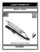
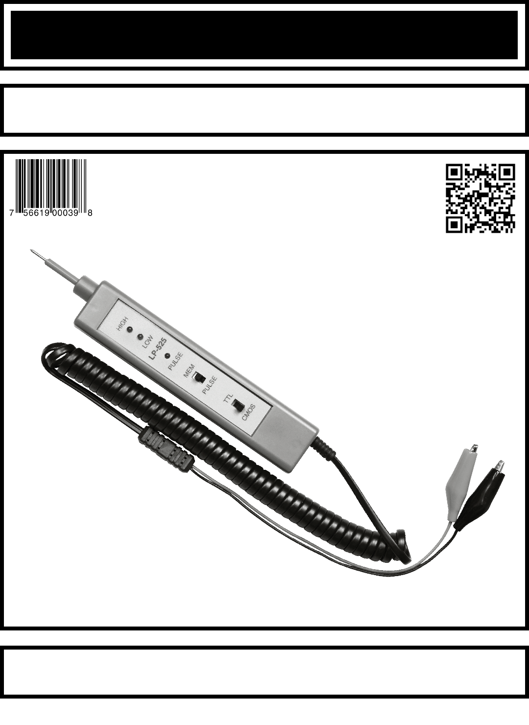
LOGIC PROBE KIT MODEL LP-525K Assembly and Instruction Manual ELENCO ® Copyright © 2013, 1994 by Elenco® Electronics, Inc. All rights reserved. Revised 2013 REV-J No part of this book shall be reproduced by any means; electronic, photocopying, or otherwise without written permission from the publisher.
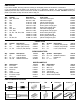
PARTS LIST If you are a student, and any parts are missing or damaged, please see instructor or bookstore. If you purchased this LP-525K Logic Probe Kit from a distributor, catalog, etc., please contact ELENCO® (address/phone/e-mail is at the back of this manual) for additional assistance, if needed. DO NOT contact your place of purchase as they will not be able to help you. RESISTORS Qty.
IDENTIFYING RESISTOR VALUES Use the following information as a guide in properly identifying the value of resistors. BAND 1 1st Digit Color Black Brown Red Orange Yellow Green Blue Violet Gray White BAND 2 2nd Digit Digit 0 1 2 3 4 5 6 7 8 9 Color Black Brown Red Orange Yellow Green Blue Violet Gray White Multiplier Digit 0 1 2 3 4 5 6 7 8 9 Color Black Brown Red Orange Yellow Green Blue Silver Gold Resistance Tolerance Multiplier 1 10 100 1,000 10,000 100,000 1,000,000 0.01 0.
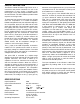
CIRCUIT DESCRIPTION The Elenco® Model LP-525K Logic Probe kit is a convenient and precise instrument for use in the measurement of logic circuits. It displays logic levels (high or low), and voltage transients down to 25 nanoseconds. The LED readouts provide instant response to the logic state. becomes more negative than the (+) input and the comparator turns off. The short pulse on the input is thus stretched to 1.5 milliseconds. The (–) input (pin 8) of the PULSE LED driver is biased to +2.
CONSTRUCTION Introduction • Turn off iron when not in use or reduce temperature setting when using a soldering station. The most important factor in assembling your LP-525K Logic Probe Kit is good soldering techniques. Using the proper soldering iron is of prime importance. A small pencil type soldering iron of 25 watts is recommended. The tip of the iron must be kept clean at all times and well-tinned. • Tips should be cleaned frequently to remove oxidation before it becomes impossible to remove.
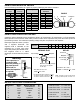
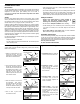
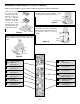
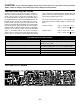
ASSEMBLE COMPONENTS TO THE PC BOARD Refer to the top legend on the PC board, install and solder the following resistors. Stand resistor on end when called for. Figure 1 R23 - 200Ω Resistor (red-black-brown-gold) (see Figure 1) R13 - 18kΩ Resistor (brown-gray-orange-gold) R1 - 100kΩ Resistor (brown-black-yellow-gold) R9 - 4.7MΩ Resistor (yellow-violet-green-gold) R24 - 200Ω Resistor (red-black-brown-gold) R10 - 20kΩ Resistor (red-black-orange-gold) R14 - 5.
ASSEMBLE COMPONENTS TO THE PC BOARD Refer to the top legend on the PC board, install and solder the following diodes, capacitors and jumper wires. When mounting diodes vertically, mount as indicated by band. (Diodes have polarity). Figure 2 Form jumper wire from discarded resistor lead. Figure 3 When mounting diodes horizontally, mount as indicated by the band. (Diodes have polarity). Figure 4 D1 - 1N4148 Diode (see Figure 2) D2 - 1N4148 Diode (see Figure 2) C1 - .
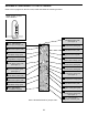
ASSEMBLE COMPONENTS TO THE PC BOARD Refer to the top legend on the PC board, install and solder the following components. Insert the IC socket into the PC board with the notch in the direction shown on the top legend. Solder the IC socket into place. Insert the IC into the socket with the notch in the same direction as the notch on the socket. Mount the transistor with the flat side in the direction shown on the top legend. Leave 1/4” between the part and PC board.
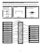
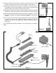
r Install the power cord as shown in Figure 9. Solder the red wire to hole marked “+” and the green wire to the hole marked “–” (see Figure 9). r Install the probe tip as shown in Figure 10. Using the 1 1/2” wire, strip 1/4” of insulation off of both ends. Solder one end to point P on the PC board. Solder the other end of the wire to the probe tip groove. Red wire (to + hole) Green wire (to – hole) r Install the two labels to the case, as shown in Figure 11.
CAUTION: Do not connect the alligator clips to any AC power source or to DC power source greater than 35VDC. Failure to comply to this warning may result in damage to this instrument. TESTING YOUR DIGITAL PROBE Checking out your Logic Probe for proper operation is fairly easy. All that is needed is a 9V battery or other DC power source (5-10V). Connect the red alligator clip to the positive terminal of the battery and the black clip to the negative terminal.
OPERATING INSTRUCTIONS To operate the logic probe, connect the two alligator clips to the circuit DC power supply, red clip to the positive voltage, black to ground. BE SURE THE CIRCUIT SUPPLY IS UNDER 35V OR DAMAGE MAY OCCUR TO THE PROBE. Set the logic family switch to TTL or CMOS. Touch the probe tip to the circuit node to be analyzed. The LED display on the probe body will light to indicate the condition of the node. Refer to the chart below to interpret the LED readings.
SCHEMATIC DIAGRAM REV-C ELENCO® 150 Carpenter Avenue • Wheeling, IL 60090 (847) 541-3800 • www.elenco.com • e-mail: elenco@elenco.