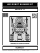
LED ROBOT BLINKER KIT MODEL K-17 Assembly and Instruction Manual ELENCO Copyright © 2011, 1998 by ELENCO® All rights reserved. ® Revised 2011 REV-O No part of this book shall be reproduced by any means; electronic, photocopying, or otherwise without written permission from the publisher.
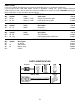
PARTS LIST If you are a student, and any parts are missing or damaged, please see instructor or bookstore. If you purchased this LED robot blinker kit from a distributor, catalog, etc., please contact ELENCO® (address/phone/e-mail is at the back of this manual) for additional assistance, if needed. DO NOT contact your place of purchase as they will not be able to help you. RESISTORS Qty. r2 r2 Symbol R2, R3 R1, R4 Value 330Ω 5% 1/4W 10kΩ 5% 1/4W Qty.
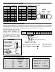
IDENTIFYING RESISTOR VALUES Use the following information as a guide in properly identifying the value of resistors. BAND 1 1st Digit Color Black Brown Red Orange Yellow Green Blue Violet Gray White BAND 2 2nd Digit Digit 0 1 2 3 4 5 6 7 8 9 Color Black Brown Red Orange Yellow Green Blue Violet Gray White Multiplier Digit 0 1 2 3 4 5 6 7 8 9 Color Black Brown Red Orange Yellow Green Blue Silver Gold Resistance Tolerance Multiplier 1 10 100 1,000 10,000 100,000 1,000,000 0.01 0.
INTRODUCTION The Robot Blinker alternately flashes a pair of LED’s (light emitting diode) on at about two blinks per second. The circuit is basically an astable multivibrator or free-running oscillator. In analyzing how it works, we will look at the start-up stage and then at the continuous cycle stage where the LED’s flash at a continuous two cycles per second. COMPONENT OPERATION Let’s first review the operation of critical components.
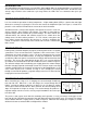
CONSTRUCTION Introduction • Turn off iron when not in use or reduce temperature setting when using a soldering station. The most important factor in assembling your K-17 LED Robot Blinker Kit is good soldering techniques. Using the proper soldering iron is of prime importance. A small pencil type soldering iron of 25 - 40 watts is recommended. The tip of the iron must be kept clean at all times and well-tinned.
ASSEMBLE COMPONENTS TO THE PC BOARD Wear safety goggles when assembling. ' D2 - LED (see Figure A) D1 - LED (see Figure A) R3 - 330Ω 5% 1/4W Resistor (orange-orange-brown-gold) R2 - 330Ω 5% 1/4W Resistor (orange-orange-brown-gold) Q1 - 2N3904 Transistor (see Figure B) Q2 - 2N3904 Transistor (see Figure B) R1 - 10kΩ 5% 1/4W Resistor (brown-black-orange-gold) R4 - 10kΩ 5% 1/4W Resistor (brown-black-orange-gold) C2 - 100μF Electrolytic Cap. (see Figure C) C1 - 100μF Electrolytic Cap.
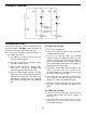
SCHEMATIC DIAGRAM TROUBLESHOOTING The LED’s will not light Consult your instructor or contact ELENCO® if you have any problems. DO NOT contact your place of purchase as they will not be able to help you. 1. Use a fresh 9 volt battery. 2. Check to see that the battery snap is correctly mounted to the PC board. One of the most frequently occurring problems is poor solder connections. 3. Check to see that the LED’s are mounted correctly. Short the cathode of LED D1 to the negative (–) battery lead.
QUIZ 1. The Robot Blinker circuit is essentially _________________. 2. The LED emits light when ____________ passes through it. 3. The transistor has three elements, name them: _____________, ____________, ____________. 4. The collector voltage must be ________ in respect to the emitter voltage. 5. For the transistor to conduct, the base must be about _____ volts above the emitter. 6. When transistor Q1 is conducting capacitor C2 will be ____________. 7.