ELECTRONIC PLAYGROUND TM and LEARNING CENTER MODEL EP-50 ELENCO ® Wheeling, IL, USA Copyright © 2010, 1998 ELENCO® 753057
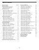
TABLE OF CONTENTS Definition of Terms Test Your Knowledge #2 Page 3 41 Answers to Quizzes 5 Experiment #25: The Magnetic Bridge 42 Introduction to Basic Components 6 Experiment #26: The Lighthouse 43 8 Experiment #27: Electronic Sound 44 10 Experiment #28: The Alarm 46 Experiment #2: Brightness Control 11 Experiment #29: Morse Code 47 Experiment #3: Resistors in Series 12 Experiment #30: Siren 48 Experiment #4: Parallel Pipes 13 Experiment #31: Electronic Rain 49 Experiment #4B
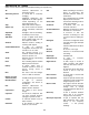
DEFINITION OF TERMS (Most of these will be introduced and explained during the experiments). AC Alternating Current AM Amp Ampere (A) Amplitude Analogy AND Gate Antenna Astable Multivibrator Atom Audio Base Battery Bias Bipolar Junction Transistor (BJT) Bistable Switch BJT Capacitance Capacitor Carbon Clockwise Common abbreviation for alternating current. A current that is constantly changing. Amplitude modulation. The amplitude of the radio signal is varied depending on the information being sent.
Electron Electronics Emitter Encode Farad, (F) Feedback Flip-Flop FM Forward-Biased Frequency Friction Gallium Arsenide Generator Germanium Ground Henry (H) Inductance Inductor Insulator Integrated Circuit Kilo- (K) A sub-atomic particle that has an electrical charge. The science of electricity and its applications. The output of an NPN bipolar junction transistor. To put a message into a format which is easier to transmit. The unit of measure for capacitance.
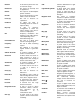
Pico- (p) Pitch Printed Circuit Board Receiver Resistance Resistor Resistor-TransistorLogic (RTL) Reverse-Biased Saturation Schematic Semiconductor Series Short Circuit A prefix used in the metric system. It means a millionth of a millionth (0.000,000,000,001) of something. The musical term for frequency. A board used for mounting electrical components. Components are connected using metal traces “printed” on the board instead of wires. The device which is receiving a message (usually with radio).
INTRODUCTION TO BASIC COMPONENTS Welcome to the exciting world of Electronics! Before starting the first experiment, let’s learn about some of the basic electronic components. Electricity is a flow of subatomic (very, very, very, small) particles, called electrons. The electrons move from atom to atom when an electrical charge is applied across the material.
The Resistor: Why is the water pipe that goes to your kitchen faucet smaller than the one that comes to your house from the water company? And why is it much smaller than the main water line that supplies water to your entire town? Because you don’t need so much water. The pipe size limits the water flow to what you actually need. Electricity works in a similar manner, except that wires have so little resistance that they would have to be very, very thin to limit the flow of electricity.
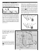
EXPERIMENT #1: The Light Bulb First, you need a 9V battery (alkaline is best). Fold out the the battery holder cutouts and snap the battery into its clip. Always remove the battery from its clip if you won’t be using your Playground for a while. 1 2 Enough talk, let’s start building your first circuit. To connect a wire to a spring, bend the spring back to one side with one finger and slip the metal end of the wire into the spring; let go of the spring and it should clamp the wire firmly in place.
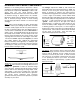
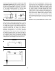
Press the switch (next to springs 55 and 56) and the LED (light emitting diode) lights up, and turns off when you release the switch. The LED converts electrical energy into light, like the light bulbs in your home. You can also think of an LED as being like a simple water meter, since as the electric current increases in a wire the LED becomes brighter. It is shown here, with its symbol. Water Meter LED Now you will see how changing the resistance in the circuit increases the current through it.
MORE ABOUT RESISTORS Ohm’s Law: You just observed that when you have less resistance in the circuit, more current flows (making the LED brighter). The relationship between voltage, current, and resistance is known as Ohm’s Law (after George Ohm who discovered it in 1828): Current = Use the color code to check the values of the seven resistors included in your Electronic Playground. (The values are marked next to them on the box). They are all 5% tolerance.
EXPERIMENT #2: The Brightness Control Connect the wires according to the Wiring Checklist. Press the switch and the LED lights up. Now hold the switch closed with one hand and turn the dial on the variable resistor with the other. When the dial setting is high, the resistance in the circuit is low and the LED is bright because a large current flows.
EXPERIMENT #3: Resistors in Series Connect the wires according to the Wiring Checklist and press the switch. The LED is on but is very dim (this will be easier to see if you wrap your hand near the LED to keep the room lights from shining on it). Take a look at the schematic. There is a low 3.3KΩ resistor and a high 100KΩ resistor in series (one after another). Since the LED is dimly lit, we know that the larger 100KΩ must be controlling the current.
EXPERIMENT #4: Parallel Pipes Connect the wires according to the Wiring Checklist. Take a look at the schematic. There is a low 3.3KΩ resistor and a high 100KΩ resistor in parallel (connected between the same points in the circuit). How bright do you think the LED will be? Press the switch and see if you are right. The LED is bright, so most of the current must be flowing through the smaller 3.3KΩ resistor.
There is an even easier way to explain this: EXPERIMENT #4B: Comparison of Parallel Currents Since we have two resistors in parallel and a second LED that is not being used, let’s modify the circuit to match the schematic below. It’s basically the same circuit but instead of just parallel resistors there are parallel resistorLED circuits. Disconnect the wire between 51 (the 100KΩ resistor) and 42 (the 3.3KΩ resistor) and connect it between 51 and 1 (LED1) instead (you may need a longer wire).
EXPERIMENT #5: Combined Circuit Let’s combine everything we’ve done so far. Connect the wires according to the Wiring Checklist. Before pressing the switch, take a look at the schematic and think about what will happen as you turn the dial on the variable resistor (we’ll abbreviate this to VR). Now press the switch with one hand and turn the dial with the other to see if you were right. As you turn the VR dial from right to left LED1 will go from bright to very dim and LED2 will go from visible to off.
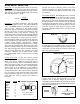
EXPERIMENT #6: Water Detector You’ve seen how electricity flows through copper wires easily and how carbon resists the flow. How well does water pass electricity? Let’s find out. 100KΩ, but depends on the local water quality). Try adding more water to the cup and see if the LED brightness changes (it should get brighter because we are “making the water pipe larger”).
INTRODUCTION TO CAPACITORS Capacitors: Capacitors are electrical components that can store electrical pressure (voltage) for periods of time. When a capacitor has a difference in voltage (electrical pressure) across it, it is said to be charged. A capacitor is charged by having a one-way current flow through it for a short period of time. It can be discharged by letting a current flow in the opposite direction out of the capacitor.
Similarly, capacitors are described by their capacity for holding electric charge, called their Capacitance, and their ability to withstand electric pressure (voltage) without damage. Although there are many different types of capacitors made using many different materials, their basic construction is the same. The wires (leads) connect to two or more metal plates that are separated by high resistance materials called dielectrics.
EXPERIMENT #7: Slow Light Bulb Connect the wires according to the Wiring Checklist and press the switch several times. You can see it takes time to charge and discharge the large capacitor because the LED lights up and goes dim slowly. Replace the 3.3KΩ resistor with the 1KΩ resistor; now the charge time is faster but the discharge time is the same.
EXPERIMENT #8: Small Dominates Large - Capacitors in Series Take a look at the schematic, it is almost the same circuit as the last experiment except that now there are two capacitors in series. What do you think will happen? Connect the wires according to the Wiring Checklist and press the switch several times to see if you are right. resistors in series add together to make a larger circuit resistance, capacitors in series combine to make a smaller circuit capacitance.
EXPERIMENT #9: Large Dominates Small - Capacitors in Parallel Now you have capacitors in parallel, and you can probably predict what will happen. If not, just think about the last experiment and about how resistors in parallel combine, or think in terms of the water diagram again. Connect the wires according to the Wiring Checklist and press the switch several times to see. both rubber diaphragms at the same time so it will take longer than to stretch either one by itself.
EXPERIMENT #10: Make Your Own Battery Connect the wires according to the Wiring Checklist, noting that there is no switch and a long wire with one end connected to the 100μF capacitor and the other end unconnected. At this time no current will flow because nothing is connected to the battery.
TEST YOUR KNOWLEDGE #1 1. __________ are the particles that flow between atoms as part of an electric current. 7. The electrical resistance of water __________ when salt is dissolved in it. 2. A __________ circuit occurs when wires or components from different parts of the circuit accidentally connect. 8. Capacitors are components __________ for periods of time. that can store 9. Capacitors have low resistance to __________ current and high resistance to __________ current. 3.
EXPERIMENT #11: One-way Current Connect the wires according to the Wiring Checklist and press the switch, the LED lights up. The diode’s turn-on voltage of 0.7V is easily exceeded and the diode has little effect on the circuit. Now reverse the wires to the diode and try again, nothing happens. The diode is now reverse-biased and blocks current flow through the circuit, just like the plate and solid stop block the water flow in the drawing shown above.
EXPERIMENT #12: One-way Lightbulbs Diodes made of Gallium Arsenide need a higher voltage across them to turn on, usually about 1.5V This turn-on energy is so high that light is generated when current flows through the diode. These diodes are the light emitting diodes that you have been using. capacitor voltage reaches the battery voltage. LED2 will not light since it is reverse-biased. Then touch the loose wire to the negative side of the battery (“ground”) and watch LED2.
INTRODUCTION TO TRANSISTORS The Transistor: The transistor was first developed in 1949 at Bell Telephone Laboratories, the name being derived from “transfer resistor”. It has since transformed the world. Did you ever hear of something called a vacuum tube? They are large and can be found in old electronic equipment and in museums. They are seldom used today and few engineers even study them now. They were replaced by transistors, which are much smaller and more reliable.
EXPERIMENT #13: The Electronic Switch Connect the wires according to the Wiring Checklist. Although there is a closed circuit with the battery, 1KΩ, LED, and transistor, no current will flow since the transistor is acting like an open circuit (with no base current the lever arm remains shut). Press the switch; a base current now flows and opens the lever arm, resulting in a large collector current which lights the LED. The transistor is being used as an electronic switch.
EXPERIMENT #14: The Current Amplifier Connect the wires according to the Wiring Checklist and press the switch. LED 1 in the collector path is brighter than LED 2 in the base path because the base current is amplified by the transistor. The current gain of a transistor varies anywhere from 10 to 1000 depending on the type of transistor, the ones in your Electronic Playground have a gain of about 200. Note that the battery voltage and circuit resistance will limit the current gain.
EXPERIMENT #15: The Substitute Look again at the water pipe analogy for the transistor, the lever pivot: What would happen if the base and collector were connected together? Once there is enough pressure to overcome the spring in check valve DE (0.7V) there would be only slight resistance and no current gain. This situation should sound familiar since this is exactly how a diode operates. When the base and collector of a transistor are connected together the transistor becomes a diode.
EXPERIMENT #16: Standard Transistor Biasing Circuit Connect the wires according to the Wiring Checklist and press the switch while turning the variable resistor from right to left (from 0Ω to 50KΩ). The 100KΩ and variable 50KΩ are a voltage divider that sets the voltage at the transistor base. If this voltage is less than 0.7V then the transistor will be off and no current will flow through the LED. As the base voltage increases above 0.
EXPERIMENT #17: Very Slow Light Bulb Connect the wires according to the Wiring Checklist and press the switch, hold it down for several seconds. The LED will slowly light up. Release the switch and the LED will slowly go dark. LED will dim as this discharge current decreases. When the capacitor voltage drops below 0.7V the transistor will turn off. If you get impatient you may touch a wire between the two capacitor springs to discharge it instantly.
EXPERIMENT #18: The Darlington This circuit is very similar to the last one. Connect the wires according to the Wiring Checklist and press the switch, hold it down for several seconds. The LED will slowly light up. Release the switch and the LED stays lit. at the base. Since there are now two transistors to turn on, the capacitor voltage must exceed 1.4V before the LED will start to light. And since the input current to the base is so small it will take much longer to discharge the capacitor.
EXPERIMENT #19: The Finger Touch Lamp Take a look at the schematic. You’re probably wondering how it can work, since nothing is connected to the transistor base. It can’t, but there is another component that isn’t shown in the schematic. That component is you. devices will have the metal contacts interweaved as shown below and will also be more sensitive so that you don’t have to wet your finger to make good contact. Connect the wires according to the Wiring Checklist.
EXPERIMENT #20: Battery Immunizer you should see LED2 change between bright and dark while LED1 remains bright as before. Connect the wires according to the Wiring Checklist and schematic. Note that the collectors of NPN2 and NPN3 are not connected although their wires cross over each other in the schematic. Connect the loose wire from spring 43 (3.3KΩ) to spring 16 (NPN1 collector, or 9V); the LED is bright. Now connect the wire to spring 17 (NPN1 emitter) instead of spring 16; the LED is just as bright.
EXPERIMENT #21: The Voltmeter Make sure you have a strong 9V battery for this experiment. Connect the wires according to the Wiring Checklist, connecting the wire to the battery last since this will turn on the circuit. And be sure to disconnect this battery wire when you’re not using the circuit to avoid draining the battery. The part of the circuit to the left of the dashed line in the schematic is the voltmeter, the two resistors on the right produce a voltage that you will measure.
EXPERIMENT #22: 1.5 Volt Battery Tester Make sure you have a strong 9V battery for this experiment. Connect the wires according to the Wiring Checklist, connecting the wire to the battery last since this will turn on the circuit. And be sure to disconnect this battery wire when you’re not using the circuit to avoid draining the battery. This circuit is a variation of the differential pair configuration used in Experiment 21, you will use it to test your 1.5V batteries. Take any 1.
EXPERIMENT #23: 9 Volt Battery Tester Make sure you have a strong 9V battery for this experiment. Connect the wires according to the Wiring Checklist, connecting the wire to the battery last since this will turn on the circuit. And be sure to disconnect this battery wire when you’re not using the circuit to avoid draining the battery. This time you will measure 9V batteries, just like the one you are using to power your Electronic Playground.
EXPERIMENT #24: The Anti-Capacitor Recall that capacitors blocked direct current (DC) but passed alternating current (AC). Take a look at Experiment 7 again and remember that it took time to light the LED because you had to charge the capacitor first; the capacitor passed the initial current surge through to ground (the negative side of the battery) but blocked the current once it stabilized, forcing it to go through the LED.
NOTES -39-
The Inductor: The inductor can best be described as electrical momentum (momentum is the power a moving object has). In our water pipe analogy the inductor can be thought of as a very long hose wrapped around itself many times as shown here: How do inductors in series and parallel add up? You saw in Experiment 24 that changing the connection point on the inductor (to reduce the length of the coiled wire) reduced LED brightness.
If you wrap two wires from different circuits around different ends of an iron bar then a current flowing through the wire from the first circuit will magnetically create a current in the wire from the second circuit! If the second coil has twice as many turns (more magnetic linkage) as the first coil then the second coil will have twice the voltage but half the current as the first coil. A device like this is called a transformer. Your Electronic Playground includes one.
EXPERIMENT #25: The Magnetic Bridge Connect the wires according to the Wiring Checklist. You are using the antenna for the first time here but only as a low-value resistor (about 10Ω); it has other properties that will be explained in later experiemnts. Press the switch several times. LED1 blinks when the switch is pressed and LED2 blinks when the switch is released. battery side of the transformer.
EXPERIMENT #26: The Lighthouse Connect the wires according to the Wiring Checklist. Notice that the transformer is being used as two coils (inductors) here. Also notice that transformer springs 23 and 24 are not connected although their wires cross in the schematic. Press the switch and hold it down for a while. The LED blinks every few seconds, like a tiny lighthouse! feedback is what turns the transistor on and off.
EXPERIMENT #27: Electronic Sound Now it’s time to make some noise. To do this we need a speaker. A speaker converts electrical energy into sound. It does this by using the energy of an AC electrical signal to create mechanical vibrations. These vibrations create variations in air pressure, called sound waves, which travel across the room. You “hear” sound when your ears feel these air pressure variations.
Schematic Wiring Checklist: o o o o o o o o o 27-to-56 55-to-24 25-to-19 20-to-26 18-to-43 5-to-21 6-to-22 42-to-31-to-33-to-35-to-37-to-44-to-46-to-53-to-51 unconnected-to-23-to-unconnected (2 loose wires) Loose Wires -45-
EXPERIMENT #28: The Alarm This circuit is unusual in that you turn it on by disconnecting a wire and turn it off by connecting the wire. Connect the wires according to the Wiring Checklist and schematic, including a long wire as the “trip” wire. Notice that there is no sound. Now disconnect the trip wire and you hear a sound, an alarm. This circuit is the same oscillator circuit you just used except that the trip wire was added.
EXPERIMENT #29: Morse Code The forerunner of today’s telephone system was the telegraph, which was widely used in the latter half of the 19th century. It only had two states – on or off (that is, transmitting or not transmitting), and could not send the range of frequencies contain in human voices or music. A code was developed to send information over long distances using this system and a sequence of dots and dashes (short or long transmit bursts). It was named Morse Code after its inventor.
EXPERIMENT #30: Siren Connect the wires according to the Wiring Checklist and press the switch. It makes a siren sound. rise slowly. As the base current slowly increases, NPN 1’s collector current also increases slowly (though it is always much higher than the base current). NPN1 is now limiting the current just as a resistor does! Similar effects occur after you release the switch and the 10μF slowly discharges.
EXPERIMENT #31: Electronic Rain Connect the wires according to the Wiring Checklist and press the switch. You hear a sound like raindrops. The variable resistor (VR) knob controls the rain, turn it to the right to make a drizzle and turn to the left to make the rain come pouring down. If you find it inconvenient to turn the VR knob while pressing the switch then just connect a wire across the switch.
EXPERIMENT #32: The Space Gun Connect the wires according to the Wiring Checklist and press the switch several times quickly. You hear a sound like a space gun in the movies. You can adjust the “gun” sound using the variable resistor. If you find it inconvenient to turn the VR knob while pressing the switch then just connect a wire across the switch.
EXPERIMENT #33: Electronic Noisemaker Connect the wires according to the Wiring Checklist, connecting the battery wire last since it will turn the circuit on. Press the switch several times quickly. Then turn the variable resistor knob to change the frequency of the sounds. Do you understand what’s happening when you press the switch? You increase the oscillator capacitance by putting the .0047μF in parallel with the .047μF, and this lowers the oscillator frequency.
EXPERIMENT #34: Drawing Resistors You need some more parts to do this experiment, so you’re going to draw them. Take a pencil (No. 2 lead is best but other types will also work), SHARPEN IT, and fill in the 4 rectangles you see below. You will get better results if you place a hard, flat surface between this page and the rest of this booklet while you are drawing.
EXPERIMENT #35: Electronic Kazoo Now it’s time to make your own music. This experiment will use the (almost) same circuit as the last one, so there is no schematic or Wiring Checklist. The only difference is that you will draw a new shape. A Kazoo is a musical instrument that is like a one-note flute, and you change the pitch (frequency) of the sound by moving a plunger up and down inside a tube. you see below.
EXPERIMENT #36: Electronic Keyboard This experiment will use the (almost) same circuit as the last one, so there is no schematic or Wiring Checklist. The only difference is that you will draw a new shape. rest of this booklet while you are drawing, Press hard (but don’t rip the paper), fill in each several times to be sure you have a thick, even layer of pencil lead, and try to avoid going out of the boundaries. Where the shape is just a line, draw a thick line and go over it several times.
EXPERIMENT #37: Fun with Water You can also make a water kazoo. Pour a small amount of water on a table or the floor and spread it with your finger into a long line. Place one of the wires at one end and slide the other along the water. You should get an effect just like the kazoo you drew with the pencil, though the frequency will probably be different. Connect the wires according to the Wiring Checklist. Initially the two loose wires are unconnected so there is no sound.
EXPERIMENT #38: Transistor Radio Back in Experiments 24 (Anti-Capacitor) and 25 (Magnetic Bridge) we talked about how an electric current through a coil creates a magnetic field and how this magnetic field can be used to “bridge” air gaps in a transformer. What if the transformer air gap was larger, perhaps a few inches? The distant coil would still pick up some of the energy, but not much.
Schematic Wiring Checklist: o o o o o o o o o o o o 28-to-9 8-to-15 7-to-29-to-32-to-51 52-to-42-to-16-to-10 33-to-31-to-17-to-20-to-48-to-26 11-to-30-to-50 49-to-34 53-to-35-to-18 19-to-23 5-to-21 6-to-22 43-to-54-to-27-to-25 -57-
EXPERIMENT #39: Radio Announcer Now that you’ve built an AM receiver, how about building an AM transmitter? Ever wanted to be a radio announcer? You’re about to get your chance. Note: you need an AM radio for this experiment. Now talk into the speaker, keeping your mouth close to it. You should hear yourself on the radio! Turn up your radio volume control or shout if you don’t hear yourself at first. You can also adjust your variable capacitor slightly to make sure you are tuned for best transmission.
Wiring Checklist: o 25-to-26-to-47-to-45to-41-to-39-to-33-to-35 o 28-to-9-to-16 o 17-to-38 o 7-to-30-to-29 o 15-to-31-to-44-to-48 o 8-to-32-to-42-to-19 o 20-to-40-to-34 o 18-to-51-to-46-to-36 o 37-to-23 o 5-to-21 o 6-to-22 o 43-to-52-to-50-to-27 EXPERIMENT #40: Radio Jammer / Metal Detector The circuit you have just built as an AM radio transmitter also has other applications. There is no schematic or Wiring Checklist here because we are using the same circuit.
EXPERIMENT #41: Blinking Lights Take a look at the schematic. This circuit configuration is a type of oscillator called an astable multivibrator. What do you think it will do? Connect the wires according to the Wiring Checklist, noting that the transistor bases are not connected although their wires cross in the schematic. Initially set the variable resistor (VR) to its minimum value (turn it to the right). Press the switch and hold it down.
EXPERIMENT #42: Noisy Blinker This circuit is similar to the last one. Connect the wires according to the Wiring Checklist (noting that the transistor bases are not connected although their wires cross in the schematic). Press the switch and hold it down. The LED lights and you hear sound from the speaker. Turn the knob on the variable resistor and the frequency of the sound changes.
EXPERIMENT #43: One-shot Do you know what this circuit will do? Connect the wires according to the Wiring Checklist (noting that the transistor bases are not connected although their wires cross in the schematic). Press the switch and release it. The LED is on for a few seconds and then goes out. What effect do you think changing the value of the variable resistor will have? Try it. The higher the resistance the longer the LED stays on.
EXPERIMENT #44: Alarm with Shut-off Timer Let’s demonstrate a use for the timer circuit you just built by combining it with Experiment 28, the Alarm. Connect the wires according to the Wiring Checklist (noting that the transistor bases and transformer springs 23 and 24 are not connected although their wires cross in the schematic). Connect the alarm trip wire and then connect the battery wire to turn the circuit on. Press the switch once. Now disconnect the trip wire to activate the alarm.
EXPERIMENT #45: The Flip-Flop This circuit is yet another variation of the basic multivibrator configuration. Connect the wires according to the Wiring Checklist. One LED will be on, the other off. Take the loose wire and touch it to the base of the transistor that is on (spring 15 or 18). That transistor turns off and the other turns on. Do this a few more times until you see that touching the “on” transistor base “flips” the transistors and the LEDs.
EXPERIMENT #46: Finger Touch Lamp with Memory Instead of using the wire to flip-flop the LED you may also use your fingers as you did in Experiment 19, the Finger Touch Lamp. We’ll use almost the same circuit here as in the last experiment. Just replace LED2 with the diode (move the wire on spring 3 to spring 10, and the wires on spring 4 to spring 11) because we don’t need two “lamps”. Wet two fingers and hold one on battery spring 27 while touching the other to the transistor base springs.
EXPERIMENT #47: This OR That Now that you’re familiar with the flip-flop, let’s introduce some more digital circuits. Digital circuits are circuits that have only two states, such as high-voltage/low-voltage, on/off, yes/no, and true/false. Connect the wires according to Wiring Checklist. Take a look at the schematic, it is very simple.
EXPERIMENT #48: Neither This NOR That a NOT gate to an OR gate to produce a NOR gate. A NOT gate is just the opposite of its input: Now let’s add on to the previous circuit by adding the wires listed in the Wiring Checklist (these are in addition to the wires from Experiment 47, which you should still have assembled).
EXPERIMENT #49: This AND That Take a look at the schematic. Can you guess what kind of digital gate this is? We’ll use almost the same circuit here as in the last experiment. Remove the wire between springs 17 and 20, and the one between springs 16 and 19. Add a wire between springs 17 and 19. Also, disconnect the 100KΩ by removing the wire between springs 19 and 52, we’ll re-connect it later. It is a NAND gate, a combination of AND and NOT.
EXPERIMENT #50: Audio AND, NAND Using the LEDs for these truth tables probably seems a little boring. So let’s use an audio circuit to make a sound instead of turning on the LED. Connect the wires according to the Wiring Checklist. Can you tell which digital gate this circuit represents? Construct the truth table to find out. You can easily modify the circuit to be an AND gate. Remove the 3.
EXPERIMENT #51: Logic Combination This last circuit is a combination of some of the other digital gates, and has 3 inputs. See if you can fill in the truth table by just looking at the schematic. Then connect the wires according to the Wiring Checklist, test all eight input combinations, and see if you were right. X Y Z LED 1 What could this circuit be used for? It might be used to provide power for your telephones.
TEST YOUR KNOWLEDGE #3 1. Adjusting the input to something based on what its output is doing is an example of __________. 5. Long wires start to act like __________ at high frequencies. 2. A speaker converts electrical energy into __________ __________ variations, called sound waves. 6. A NOR gate followed by a NOT gate is the same as an __________ gate. 3. An oscillator’s frequency __________ when you add resistance or capacitance. 7.
Elenco® Electronics, Inc. 150 Carpenter Avenue Wheeling, IL 60090 (847) 541-3800 Website: www.elenco.com e-mail: elenco@elenco.