BASIC ELECTRONIC COMPONENTS MODEL ECK-10 Resistors Capacitors Coils Others Transformers Semiconductors Instruction Manual by Arthur F. Seymour MSEE It is the intention of this course to teach the fundamental operation of basic electronic components by comparison to drawings of equivalent mechanical parts. It must be understood that the mechanical circuits would operate much slower than their electronic counterparts and one-to-one correlation can never be achieved.
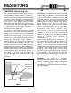
RESISTORS RESISTORS, What do they do? Electrons flow through materials when a pressure (called voltage in electronics) is placed on one end of the material forcing the electrons to “react” with each other until the ones on the other end of the material move out. Some materials hold on to their electrons more than others making it more difficult for the electrons to move.
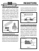
RESISTORS RESISTORS, How are they made? The value of wirewound resistors remain fairly flat with increasing temperature, but change greatly with frequency. It is also difficult to precisely control the value of the resistor during construction so they must be measured and sorted after they are built. There are many different types of resistors used in electronics. Each type is made from different materials. Resistors are also made to handle different amounts of electrical power.
RESISTORS CARBON FILM RESISTORS THE VARIABLE RESISTOR Carbon film resistors are made by depositing a very thin layer of carbon on a ceramic rod. The resistor is then protected by a flameproof jacket since this type of resistor will burn if overloaded sufficiently. Carbon film resistors produce less electrical noise than carbon composition and their values are constant at high frequencies.
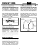
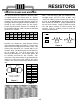
RESISTORS RESISTOR VALUES AND MARKINGS Note: If the third ring is gold, you multiply the first two digits by 0.1 and if it is silver, by 0.01. This system can identify values from 0.1Ω to as high as 91 x 109, or 91,000,000,000Ω. The amount of power each resistor can handle is usually proportional to the size of the resistor. Figure 8 shows the actual size and power capacity of normal carbon film resistors, and the symbols used to represent resistors on schematics.
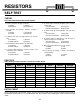
RESISTORS SELF TEST THEORY Circle the letter that best fits the description. 1. A flow of electrons through a material: a) Voltage c) Current b) Resistance d) Conductance 6. A resistor that is made by wrapping a wire around a ceramic rod: a) Carbon Film c) Thermistor b) Carbon Composition d) Wirewound 2. The pressure that pushes electrons through a material: a) Voltage c) Conduction b) Current d) Resistance 7.
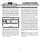
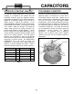
CAPACITORS CAPACITORS, What do they do? Capacitors are components that can store electrical pressure (Voltage) for long periods of time. When a capacitor has a difference in voltage (Electrical Pressure) between its two leads it is said to be charged. A capacitor is charged by forcing a one way (DC) current to flow through it for a short period of time. It can be discharged by letting an opposite direction current flow out of the capacitor.
CAPACITORS CAPACITORS, How are they made? There are many different types of capacitors used in electronics. Each type is made from different materials and with different methods. Capacitors are also made to handle different amounts of electrical pressure or voltage. Each capacitor is marked to show the maximum voltage that it can withstand without breaking down. All capacitors contain the same fundamental parts, which consist of two or more conductive plates separated by a nonconductive material.
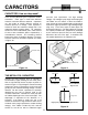
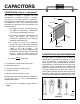
CAPACITORS DIELECTRIC CONSTANT, What is it? THE VARIABLE CAPACITOR The dielectric (rubber diaphragm in the water pipe analogy) in a capacitor is the material that can withstand electrical pressure (Voltage) without appreciable conduction (Current). When a voltage is applied to a capacitor, energy in the form of an electric charge is held by the dielectric. In the rubber diaphragm analogy the rubber would stretch out and hold the water back. The energy was stored in the rubber.
CAPACITORS CAPACITANCE, How is it calculated? The amount of charge a capacitor can hold (capacitance) is measured in Farads. In practice, one farad is a very large amount of capacitance, making the most common term used micro-farad or one millionth of a farad. There are three factors that determine the capacitance that exist between two conductive plates: 0.01 inch Glass K=10 1. The bigger the plates are (Surface Area), the higher the capacitance. Capacitance (C) is directly proportional to Area (A). 2.
CAPACITORS Voltage 1 Code 2 Cap. Value 3 Typical Markings 4 5 4 5.5 6.3 10 16 25 35 50 63 80 100 110 125 160 180 200 220 250 315 0G 0L 0J 1A 1C 1E 1V 1H 1J 1K 2A 2Q 2B 2C 2Z 2D 2P 2E 2F 100pF .001μF .015μF .002μF .0022μF .003μF .033μF .047μF .05μF .068μF .1μF .15μF .2μF 2.2μF 22μF 100μF 220μF 470μF 1000μF 100pF .001 .015 .002 .0022 .003 .033 .047 .05 .068 .1 .15 .2 2.
CAPACITORS SELF TEST THEORY Circle the letter that best fits the description. 1. A flow of electrons in one direction: a) AC Voltage c) Alternating Current b) Direct Voltage d) Direct Current 7. When electrons are forced onto one plate of a capacitor: a) Polarization c) Storage b) Discharging a) Charging 2. When two conductive plates are moved closer together Capacitance will: a) Increase c) Stay the Same b) Decrease d) Vary Downwards 8.
INDUCTORS INDUCTORS, What do they do? The electronic component known as the inductor is best described as electrical momentum. In our water pipe analogy the inductor would be equivalent to a very long hose that is wrapped around itself many times (see Figure 18). If the hose is very long it will contain many gallons of water. When pressure is applied to one end of the hose, the thousands of gallons of water would not start to move instantly.
INDUCTORS INDUCTORS, How are they made? In order to understand how inductors are made, we have to change our water pipe analogy slightly to include the effect of magnetic fields. Consider two pipes filled with water and small magnets attached to the walls of the pipes with rubber bands as shown in Figure 19. The moving magnets, due to the original current, pull the magnets in the second pipe and force a small current to flow in the same direction as the original current.
INDUCTORS INDUCTANCE, How is it calculated? Reviewing how coils are made will show the following: Where: 1. Inductance of a coil is indirectly proportional to the length of the coil. N = Number of turns 2. Inductance is directly proportional to the cross sectional area. A = Cross-sectional area of coil, in square inches L = Inductance in microhenrys μ = Permeability of core material l = Length of coil in inches 3. Inductance is proportional to the square of the number of turns.
INDUCTORS XL r TWO MORE LAWS ABOUT INDUCTORS THE Q FACTOR IN COILS Faraday’s Law states that any time a conductor moves through a magnetic field (Figure 23) a voltage is generated. Because of this principle, it is possible to attach a magnet (or coil) to a rotating device and produce large amounts of electrical power (the Hoover Dam for example). The Q (figure of merit) of a coil is the ratio of the inductive reactance to the internal series resistance of the coil.
INDUCTORS SELF TEST THEORY Circle the letter that best fits the description. 1. The inductor is best described as: a) Induced Voltage c) Electrical Storage Device b) Long Wire d) Electrical Momentum 7. When an iron core is placed into the center of a coil, the inductance will: a) Increase c) Stay the Same b) Decrease 2. When wires in a coil are moved closer together, the inductance will: a) Increase c) Stay the Same b) Decrease 8.
SEMICONDUCTORS THE DIODE, what is it? THE TRANSISTOR, what is it? The diode can be compared to the check valve shown in Figure 26. The basic function of a check valve is to allow water to flow in only one direction. Once the force of the spring is exceeded, the plate moves away from the stop allowing water to pass through the pipe. A flow of water in the opposite direction is blocked by the solid stop and plate. If it took a pressure of 0.
SEMICONDUCTORS THE PNP TRANSISTOR Since there are no check valves, the current can flow in either direction. In other words, this device acts like a variable resistor. The Field Effect Transistor (FET) also controls current between source and drain by “pinching off” the path between them. The level of voltage on the gate controls the amount of current that will flow.
SEMICONDUCTORS THE INTEGRATED CIRCUIT If the water pipe analogies of the resistor, diode, transistor, and very small capacitors could be etched into a single block of steel you would have the equivalent of the Integrated Circuit in Electronics. Figure 31 represents such a device. This block of steel would have to be very large to include all the mechanical parts needed. In electronics, the actual size of a diode or transistor is extremely small.
SEMICONDUCTORS SELF TEST THEORY Circle the letter that best fits the description. 1. The diode is best described as: a) Switch c) Electrical Storage Device b) Check Valve d) Electrical Momentum 6. A diode made of Gallium Arsenide is called: a) Zener Diode c) LED b) Power Diode d) Detector Diode 2. A silicon diode begins to conduct current at approximately: a) 7 volts c) 0.7 lb. b) 0.7 volts d) 7 lbs. 7.
MECHANICAL PARTS PRINTED CIRCUIT BOARDS, What are they? A printed circuit is a conductive pattern glued to one or both sides of an insulating material. Holes are punched or drilled through the conductor and board to allow the interconnection of electronic parts. In the case of a double sided board, the holes are plated to provide a connection between the conductors on both sides of the board.
MECHANICAL PARTS THE TOP LEGEND SOLDER, The Electronic Glue The component side of a printed circuit board should always have a drawing showing the placement of the parts and their schematic marking (R1, R2, etc.). This drawing is called the Top Legend. When a board needs to be repaired, the schematic becomes the “road map” and the top legend becomes the “address” on the part. Figure 35 shows the correlation between the Schematic and the Top Legend. Different parts have been discussed.
MECHANICAL PARTS OTHER MECHANICAL PARTS MOUNTING HARDWARE There are many other mechanical parts used by manufacturers of electronic equipment. Most of them fall into the category of switching or connecting circuits. In Figure 36, five of the six parts shown are used to switch or connect signals to the printed circuit board. Only the spacer falls into a different category, called mounting. The switch is used to redirect current or voltage from one circuit to another.
MECHANICAL PARTS SELF TEST THEORY Circle the letter that best fits the description. 1. Copper patterns on a Printed Circuit Board should always be: a) As thin as possible c) Rounded b) Sharp and square d) On one side only 5. The material the copper is glued to on a printed circuit board is called a: a) Conductor c) Resistor b) Semiconductor d) Insulator 2.
ANSWERS TO QUIZZES PAGE 5 1.c 2.a 3.d 4.a 5.c 6.d 7.b 8.a 9.b 10.
EDUCATION KITS Complete with PC Board and Instruction Book Space War Gun 0-15V Power Supply Christmas Tree K-10 K-11 K-14 K-17 Rapid fire or single shot with 2 A low-cost way to supply Produces flashing flashing LEDs. voltage to electronic games, colored LEDs etc. and three popular Christmas melodies. Requires 9V battery Requires 9V battery Digital Bird Nerve Tester Yap Box K-19 K-20 K-22A You probably have never heard Test your ability to a bird sing this way before. remain calm.
ELENCO® 150 Carpenter Avenue Wheeling, IL 60090 (847) 541-3800 Website: www.elenco.com e-mail: elenco@elenco.