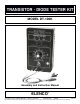
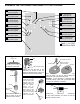
TRANSISTOR - DIODE TESTER KIT MODEL DT-100K Assembly and Instruction Manual ELENCO ® Copyright © 2014, 1988 by ELENCO® All rights reserved. Revised 2014 REV-R No part of this book shall be reproduced by any means; electronic, photocopying, or otherwise without written permission from the publisher.
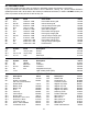
DT-100 PARTS LIST If you are a student, and any parts are missing or damaged, please see instructor or bookstore. If you purchased this transistor–diode tester kit from a distributor, catalog, etc., please contact ELENCO® (address/phone/e-mail is at the back of this manual) for additional assistance, if needed. DO NOT contact your place of purchase as they will not be able to help you. RESISTORS Qty.
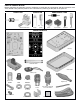
PARTS VERIFICATION Before beginning the assembly process, familiarize yourself with the components and this instruction book. Verify that all of the parts are present. This is best done by checking off the parts in the parts list. RESISTORS CAPACITOR SEMICONDUCTORS Diode Carbon film 100kΩ Potentiometer Discap Electrolytic (radial) 555 IC 8-pin Socket Transistor LED MISCELLANEOUS Case top PC Board Label Lead-free solder Case bottom Switch DPDT Battery snap Spacer LED Screws 2.
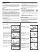
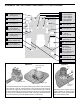
CONSTRUCTION Introduction • Turn off iron when not in use or reduce temperature setting when using a soldering station. The most important factor in assembling your DT-100K Transistor Diode Kit is good soldering techniques. Using the proper soldering iron is of prime importance. A small pencil type soldering iron of 25 watts is recommended. The tip of the iron must be kept clean at all times and well-tinned. • Tips should be cleaned frequently to remove oxidation before it becomes impossible to remove.
ASSEMBLE THE FOLLOWING COMPONENTS TO THE PC BOARD R4 - 330kΩ Resistor (org-org-yel-gold) R1 - 330Ω Resistor (org-org-brn-gold) J1 - Jumper Wire (see Figure A) R3 - 33kΩ Resistor R2 - 33kΩ Resistor (org-org-org-gold) R5 - 220Ω Resistor R6 - 220Ω Resistor (red-red-brn-gold) R9 - 47kΩ Resistor (yel-vio-org-gold) R13 - 1kΩ Resistor (brn-blk-red-gold) R8 - 18kΩ Resistor (brn-gray-org-gold) R12 - 10kΩ Resistor (brn-blk-org-gold) R7 - 5.
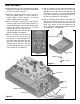
ASSEMBLE THE FOLLOWING COMPONENTS TO THE PC BOARD L1 L4 L2 L5 L3 Q1 - 2N3904 Transistor (see Figure B) C1 - 10µF Electrolytic (see Figure C) Q5 - MPS A70 Transistor (see Figure B) - LED & Spacer - LED & Spacer - LED & Spacer - LED & Spacer - LED & Spacer (see Figure D) Q4 - 2N3904 Transistor (see Figure B) C3 - .01µF Discap C2 - .
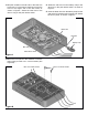
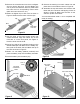
FINAL ASSEMBLY r Peel the backing off of the front label and carefully adhere it to the top case, aligning the holes while doing so, as shown in Figure I. r Strip ¼” insulation off both ends of the yellow wire and insert one end into hole “B” on the blue legend side of the PC board and solder the wire into place. Tie a knot 2 ½” from the soldered end of the wire. Pull the free end through the hole of the top case marked “B”, see Figure K.
r Strip the insulation off both ends of the blue wire to expose 1/4” of bare wire. Solder one end to the hole on the copper side of the PC board, as shown in Figure L. Solder the other end of the wire to a lug on the push button switch. r Solder the red wire from the battery snap to the other lug on the push button switch, as shown in Figure L. r Insert the black wire from the battery snap into the pad on the PC board from the copper side. Solder the wire in place, as shown in Figure L.
r Remove the colored boots from the four alligator clips (to remove the boots, clip the alligator clip onto a pencil and slide the boot off). Slide each boot onto the four corresponding colored wires (black boot onto black wire, etc.). r Remove the backing from each rubber foot and place them in the locations shown in Figure Q. r Assemble the top and bottom case sections and fasten with four 2.8 x 8mm self-tapping screws as shown in Figure Q. Make sure the slots on the side line up with one another.
CHECKING OUT YOUR TRANSISTOR/DIODE TESTER The following is a simple procedure for testing your DT-100. If the tests fail, refer to the troubleshooting guide for help. Diode Operation: Transistor Operation: (using leads) 1. Place the switch in the diode position. Short the black and red leads together and push in the test button. The diode test LEDs should alternately go on at about a 1Hz rate. 1. Place the switch in transistor position. Short the yellow (B) and black (E) leads together.
THEORY OF OPERATION Note the schematic diagram on the back cover of this manual. The test transistor in this circuit is a NPN. Adjusting the variable resistor will cause the NPN LED to light, indicating that base current is flowing. The output of the test transistor is fed to amplifier Q2 and Q3. The output of Q2 is fed back in phase to the base of the test transistor causing the circuit to oscillate. Part of the oscillations are fed to a power rectifier Q5 which switches on the OK LED indicator.
ELENCO® 150 Carpenter Avenue • Wheeling, IL 60090 (847) 541-3800 • www.elenco.com • e-mail: elenco@elenco.