
Instruction Manual


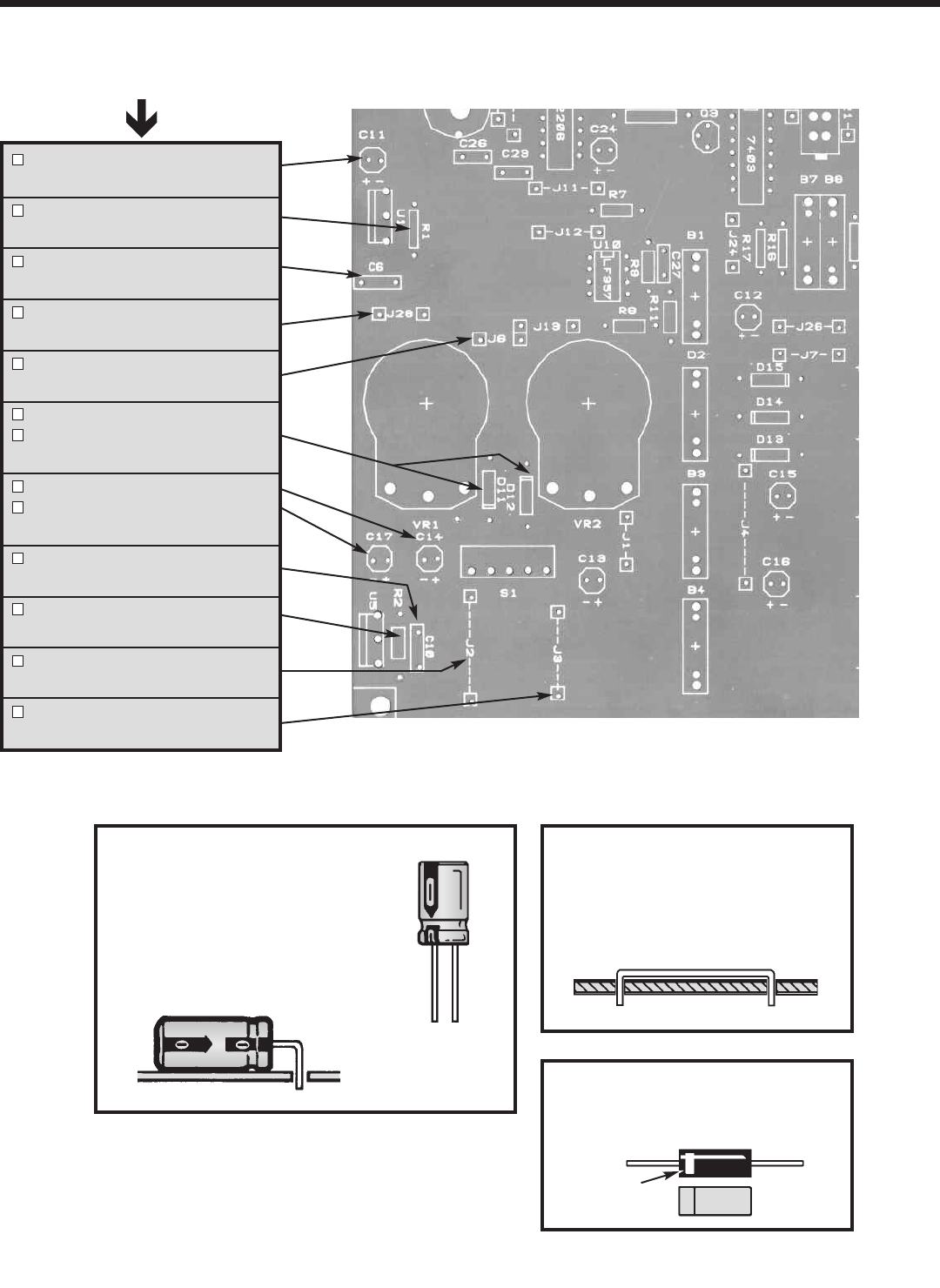
Figure G
Diodes have polarity. Mount them
with the band as shown on the top
legend.
-6-
INSTALL COMPONENTS TO PC BOARD
C11 - 100µF 25V
(see Figure E)
R1 - 120Ω 5% 1/4W Resistor
(brown-red-brown-gold)
C6 - .1µF Mylar (104)
(see Figure D)
J28 - Jumper Wire
(see Figure F)
J6 - Jumper Wire
(see Figure F)
D12 - 1N4001 Diode
D11 - 1N4001 Diode
(see Figure G)
C14 - 100µF 25V Lytic
C17 - 100µF 25V Lytic
(see Figure E)
C10 - .1µF Mylar (104)
(see Figure D)
R2 - 120Ω 5% 1/4W Resistor
(brown-red-brown-gold)
J2 - Jumper Wire
(see Figure F)
J3 - Jumper Wire
(see Figure F)
Figure F
Cut a piece of the #22 bare wire
long enough so that 1/4” of wire
passes through each hole in the
PC board after the wire is formed.
Band
Bottom Left Corner of PC Board
Figure E
These capacitors are polarized. Be
sure to mount them with the “+”
lead in the correct hole as marked
on the PC board. Mount the
capacitor lying flat on the PC board
as shown below.
(+)
(–)
Start Here