
Instruction Manual


-16-
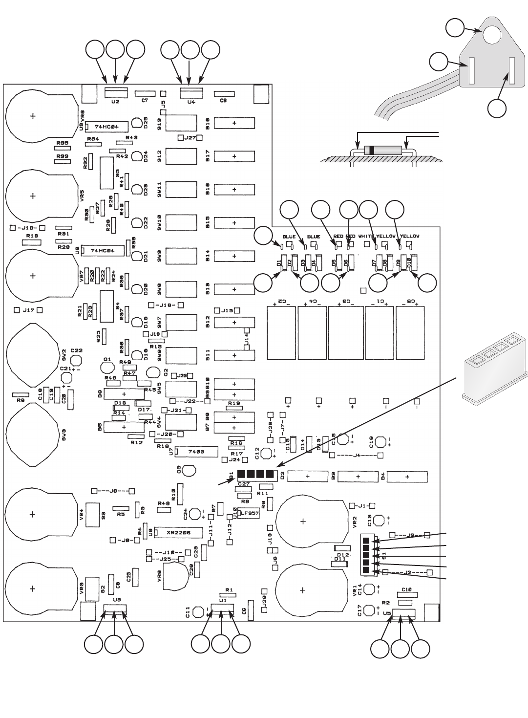
Locations for Testing Points
•••
21
19
26
•••
18
20
25
•••
22
27
17
5-pin connector left
5-pin connector +20
5-pin connector right
5-pin connector –20
GND
Ground
•••
29
16
24
•••
15
28
23
9
8
7
6
5
4
10
11
12
13
14
+20V
Pot
Figure V
B1
LM-7812 LM-7912
LM-7805 LM-317
LM-337
On test points 4 - 14
use the leads of the
diodes.
Plug of line cord
1
3
2
–20V
Pot