
User guide


-2-
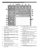
USERS DESCRIPTION OF FRONT PANEL CONTROL
1) Fuse holder - Easy access for replacement of
1.25A 250V fuse.
2) On-Off switch - Allows power to be applied to
all outputs. Switch will light when on.
3) Power output terminals - This provides
30VAC center tapped at 15VAC - also provides
output terminal for positive and negative
variable voltages.
4) Variable positive voltage control - Varies
positive voltage from 0 to 20V at indicated
output terminal.
5) Variable negative voltage control - Varies
negative voltage from 0 to –20V at indicated
output connector pin.
6) Output terminals for 1kΩ and 100kΩ
undedicated potentiometers.
7) 1kΩ undedicated potentiometer.
8) 100kΩ undedicated potentiometer.
9) Waveform selection control, square, triangle
or sine generator waveforms.
10) Output terminals for all functions as stated, 4
pins per block.
11) Two logic switches - These are no bounce
logic switches. Give one signal state change
per movement of switch.
12) Selects five ranges of frequencies from 10 to
100,000 hertz.
13) Fine frequency control - allows easy selection
of desired function generator frequency.
14) Amplitude control - Controls the function
generation output amplitude, 0-15Vpp.
15) DC offset control - controls the DC level of the
generator output. DC may be varied +
10 volts
from zero level.
16) Input points for logic indicator LEDs. “A”
input corresponds with A lamp, etc.
17) Logic indicators LEDs, total eight.
18) Eight data switches - Output 5V or 0V
depending on position.
19) Output terminals for all functions as stated, 4
pins per block.
20) Two breadboards containing a total of 1,660
tie points including 6 independent bus lines.
1
2
3
4
5
6
7 8 13 14 15
16
17
18
19
20
1211109