
User guide


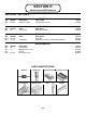


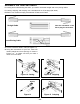

! 1. Connect the battery to the battery snap.
! 2. Push the switch SW1. Two vertical LEDs
should be blinking at a frequency of
approximately 8Hz.
! 3. Test the other pairs of LEDs by pushing switch
SW1. For every step, there should be only two
vertical blinking LEDs. If not, then:
a) Check U2, U3, C4 and diodes D1-D16.
Be sure that they are installed as shown
in the assembly instructions.
b) Check that the resistors R1-R8 installed
are the correct values.
c) Check the soldering on the modular jack
and F-connector.
TESTING
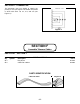
Figure 10
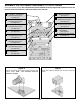
SECTION D - SWITCHES AND LED INDICATOR
In this section, two quad analog switches
(74HC4066) and 16 LEDs are used to indicate
which pins are being tested and the type of cable.
Figure 8 shows the logic diagram for each switch.
Each switch contains an input, output and a control
pin. The inputs are connected to the oscillator
section and the outputs to two LEDs and connector.
The control pins connect to the outputs of the 4017
IC (see Figure 10).
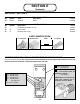
When switch A is closed, capacitor C charges and
discharges at the oscillator frequency. This causes
LEDs D1 and D2 to blink at the same rate (see
Figure 9a).
Connecting a straight cable, LED D3 will light only
during the charging cycle. The diode in the
terminator only allows the current flow in one
direction (see Figure 9b).
Connecting a cross-pinning cable, LED D4 will light
only during the discharging cycle (see Figure 9c).
Figure 8
Without Terminator
Figure 9a
ON/OFF Control
Analog
Input/Output
Analog
Output/Input
-15-
{
From
Counter
From Oscillator
Charge
Discharge
Straight Cable
Figure 9b
Cross-Pinning Cable
Figure 9c
A
B
A
B
A
B