
User guide


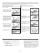
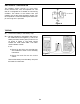

! 1. Connect the battery to the battery snap.
! 2. Set the voltmeter to read 20VAC and connect
the COM lead to the negative (–) side of the
battery and the V lead to pad of pin 8 of IC U3
as shown in Figure 5. The meter should
indicate 0V. Push switch SW1. The meter
should indicate 3-5VAC.
If not:
a) Check U5 and C3 to be sure that they
are installed as shown in the assembly
instructions.
b) Check R13 and R14 are the correct
values.
Remove the battery from the battery snap and
the leads from the tester.
-9-
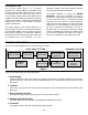
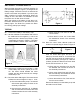
SECTION B - OSCILLATOR
The oscillator section consists of a 555 timing
circuit, resistors R13, R14, and capacitor C3. The
555 IC is configured as an astable or free-running
oscillator. The values of the resistor R14 and
capacitor C3 set the output frequency at 8Hz. The
IC will produce a continuous 8Hz square wave from
pin 3 as long as it is powered.
TESTING
Figure 4
To Switches
Figure 5
V
COM
VAC
+
9V
1
14