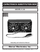
CAPACITANCE SUBSTITUTION BOX MODEL K-38 Assembly and Instruction Manual Elenco Electronics, Inc. ® Copyright © 2008, 1989 by Elenco® Electronics, Inc. All rights reserved. Revised 2008 REV-J No part of this book shall be reproduced by any means; electronic, photocopying, or otherwise without written permission from the publisher.
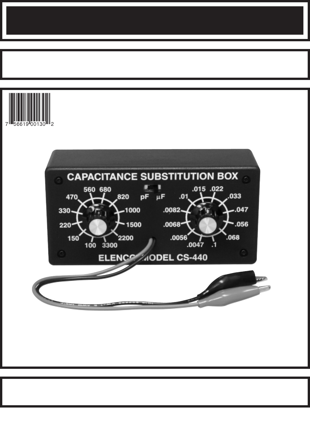
The Capacitance Substitution Box is a convenient instrument in determining the desired capacitance values in circuits under design or test. The values selected for your capacitance substitution box were determined to be the most commonly used in modern solid-state circuits. The values are from 100pF to .1μF in 24 steps. PARTS LIST If you are a student, and any parts are missing or damaged, please see instructor or bookstore. If you purchased this kit from a distributor, catalog, etc.
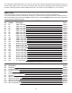
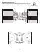
PARTS IDENTIFICATION Switch PC Mount 9mm Nut Switch 12 Position Washer Alligator Clip Capacitor PC Board IDENTIFYING CAPACITOR VALUES Capacitors will be identified by their capacitance value in pF (picofarads), nF (nanofarads), or μF (microfarads). Most capacitors will have their actual value printed on them. Some capacitors may have their value printed in the following manner. The maximum operating voltage may also be printed on the capacitor.
CONSTRUCTION Introduction The most important factor in assembling your K-38 Capacitance Substitution Box Kit is good soldering techniques. Using the proper soldering iron is of prime importance. A small pencil type soldering iron of 25 40 watts is recommended. The tip of the iron must be kept clean at all times and well tinned. Safety Procedures • • • • Wear eye protection when soldering and during all phases of construction.
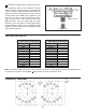
ASSEMBLY INSTRUCTIONS Begin the PC board assembly with the 100pF capacitor placed in position R1. Be sure to identify the correct value. Bend the leads to fit. Place the capacitor into the PC board with the leads coming out on the copper foil side. Solder into place and clip off the excess leads. R9 - 1000pF (102) 50V Cap. R22 - .056μF (563) 100V Cap. R7 - 680pF (681) 50V Cap. R24 - .1μF (104) 100V Cap. R8 - 820pF (821) 50V Cap. R23 - .068μF (683) 100V Cap. R10 - 1500pF (152) 50V Cap. R21 - .
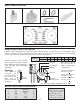
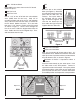
SW3 - PC Mount Switch SW1 Mount SW3 in the place shown on the PC board. Solder into place. SW2 Bend the tab on the switches down (see Figure 2). Attach the two switches loosely to the front panel with the 9mm nuts and washers. Line up the holes of the PC board with the switch lugs, as shown in Figure 3. Be sure that the board lays flat, then solder the lugs into place. Tighten down the 9mm nuts.
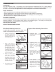
Installation of Knobs without Capacitance Meter PC Board If a capacitance meter is not available, turn both switches so that the wiper contact is in the position shown in Figure 5. Start with switch SW1, follow the copper run on the PC board from the lug in contact with the wiper to the 680pF (R7) capacitor, to be sure that the switch is set in the proper position. Align the knob on the SW1 (PFD) switch to the 680pF position, push the knob onto the shaft.
Elenco® Electronics, Inc. 150 Carpenter Avenue Wheeling, IL 60090 (847) 541-3800 Website: www.elenco.com e-mail: elenco@elenco.