
Manual


-99-
T
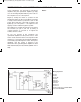
he LED circuits in experiments 78 and 79
(“Operational Amplifier Blinking LED” and “LED
F
lasher”) each use one LED, but the circuit in this
project uses two LEDs that take turns lighting. Slide
the switch to position B and assemble the circuit.
Then, turn the power on by sliding the switch to
position A and wait for a few seconds. The LEDs
light and turn off in rotation.
The operational amplifier works as an astable
multivibrator. When the output is low, LED 2 lights;
when it is high, LED 1 lights.
You can alter the speed of the blinking by using
different values for R and C. See how the speed of
the pulses alters when you alter the value of R to
220kW.
N
otes:
EXPERIMENT #80: DOUBLE LED BLINKER
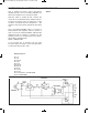
Schematic
Wiring Sequence:
o 31-36-67-90-94
o 33-70-135
o 34-63-132
o 93-68-113
o 81-89-69
o 82-114-124-119
o 121-134
o 122-131
EP-130_62315RevC.qxp_EP-130_062812 6/23/15 11:17 AM Page 99