
Manual


-94-
T
his is the last in the series of microphone
amplifiers. Now you will use the operational
amplifier as a differential amplifier. It is a two-power
s
ource type amplifier, and this time we use the
speaker as a microphone.
Slide the switch to position B and construct the
circuit. When you finish the wiring, apply the
earphone to your ear, slide the switch to position A
to turn on the power, and tap the speaker lightly with
your finger.
In this circuit the operational amplifier is configured
to amplify the difference between its positive (+) and
negative (–) inputs, so we call it a differential
amplifier. The speaker is connected to the
transformer, which is then connected to the
amplifier’s inputs, so the speaker signal will be
amplified.
In a speaker, an electrical signal flows through a coil
and creates a magnetic field; the magnetic field
changes as the electrical signal changes. The
magnetic field is used to move a small magnet, and
this movement creates variations in air pressure,
which travel to your ears and are interpreted as
sound.
This circuit uses the speaker as a microphone. In
this arrangement, your voice creates variations in
air pressure, which move the magnet inside the
speaker. The moving magnet’s magnetic field
creates an electrical signal across both ends of a
coil. This small signal is applied to the primary of the
transformer, which then results in larger signal at
the secondary side of the transformer.
T
his circuit is simplified by using the speaker as a
microphone. To use the earphone as in previous
experiments, you would have to make a far more
c
omplex circuit.
Notes:
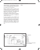
EXPERIMENT #75: DUAL-SUPPLY DIFFERENTIAL AMPLIFIER
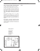
Wiring Sequence:
o 1-29
o 2-30
o 3-110
o 5-68-93
o 63-131
o 69-81-109
o 70-134
o 121-135
o 122-132
o 124-119-82-13-EARPHONE
o 94-67-14-EARPHONE
Schematic
EP-130_62315RevC.qxp_EP-130_062812 6/23/15 11:17 AM Page 94