
Manual


-93-
In Projects 72 and 73 (“Non-inverting Dual Supply
Op Amp,” and “Inverting Dual Supply Op Amp,”
r
espectively), we used the operational amplifier with
t
wo power sources. In this experiment, we will make
a single-power source, non-inverting microphone
amplifier. Again, the earphone works as a
microphone.
Slide the switch to position B and assemble the
circuit. When you competed the wiring, slide the
switch to position A to turn on the power, alternate
the control clockwise, and speak into the
microphone. The experiment works just like
Projects 72 and 73, but you’ll notice something
different.
The contrast comes from the gain of this
microphone amplifier. It is still determined by R1
and R2, but now it’s much bigger. Can you observe
why? Yes, we use the 100W resistor in place of the
1kW resistor from the last two experiments. Try
changing R2 to 1kW, and the gain drops to the level
of the last experiments.
In this experiment, two power sources are
connected in series to operate the dual operational
amplifier at 9V. But the operational amplifier can
work at half this voltage, at 4.5V. See what occurs
when you disconnect the operational amplifier from
battery terminal 122 and connect it to terminal 119.
Notes:
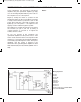
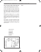
EXPERIMENT #74: NON-INVERTING AMPLIFIER
Wiring Sequence:
o 1-29
o 2-30
o 3-116
o 27-112
o 71-114
o 81-63-131
o 67-90-115
o 89-68-113
o 84-82-69-111
o 119-124
o 122-132
o 121-26-70-83-72-5-14-EARPHONE
o 28-13-EARPHONE
Schematic
EP-130_62315RevC.qxp_EP-130_062812 6/23/15 11:17 AM Page 93