
Manual


-92-
T
his is another two-power source microphone
amplifier, but this one is an inverting amplifier. You
will use the earphone as a microphone again.
Slide the switch to position B and construct the
circuit. Once you finish the wiring, slide the switch to
position A to turn the power on, adjust the control
clockwise, and speak into the “microphone” – the
earphone. This project works just like the preceding
one.
IC 2 is an inverting amplifier and IC 1 is used as a
buffer between the earphone and IC2, and has a
gain of 1. IC2 is an inverting amplifier, with the input
applied through its negative (–) terminal, not the
positive (+) one as in our last project. IC2’s gain is
about 100, as determined by:
R1/R2 = 100k/1k=100.
If you increase R1 or decrease R2, the gain
becomes larger. See what occurs to the gain when
you alter the value of R2 to 470.
N
otes:
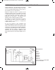
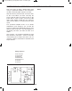
EXPERIMENT #73: INVERTING DUAL SUPPLY OP AMP
Wiring Sequence:
o 1-29
o 2-30
o 3-64-90
o 27-69
o 63-131
o 65-89-76
o 68-67-75
o 70-134
o 121-135
o 122-132
o 124-119-26-66-5-14-EARPHONE
o 28-13-EARPHONE
Schematic
EP-130_62315RevC.qxp_EP-130_062812 6/23/15 11:17 AM Page 92