
Manual


-91-
In this experiment, you will make a microphone
amplifier, using the operational amplifier (op amp)
a
s a non-inverting amplifier with two power sources.
T
he earphone acts as a microphone.
Begin by sliding the switch to position B and
finishing the wiring for the circuit. When your wiring
is ready, set the switch to position A to turn on the
power. Now rotate the control fully clockwise, and
lightly tap your “microphone” – the earphone. The
tapping sound is heard through the speaker.
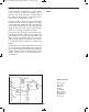
The earphone is a better microphone if you remove
the end that you put in your ear, by turning it
counter-clockwise to unscrew it. To adjust the
volume, turn the control.
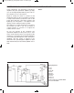
As you can observe in the schematic, the
operational amplifier uses two power sources: 4.5V
for the circuit and 9V for the IC. The signal from the
earphone is connected to the operational amplifier’s
non-inverting input through the control. The input is
amplified, and the output is applied to the
transformer. The gain through the amplifier is about
100, determined by the ratio R1/R2 (100kW / 1kW =
100).
Notes:
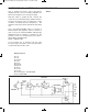
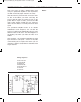
EXPERIMENT #72: NON-INVERTING DUAL SUPPLY OP AMP
Wiring Sequence:
o 1-29
o 2-30
o 3-67-90
o 27-69
o 63-131
o 68-89-75
o 70-134
o 121-135
o 122-132
o 124-119-26-76-5-14-EARPHONE
o 28-13-EARPHONE
Schematic
EP-130_62315RevC.qxp_EP-130_062812 6/23/15 11:17 AM Page 91