
Manual


F
or this section you will need some basic
understanding about the operational amplifier
integrated circuit. First, we can use separate power
s
ources or we can use one power source for both
the circuit and the IC.
The operational amplifier (often called “op amp” for
short) can be operated as a non-inverting amplifier,
an inverting amplifier, or a differential amplifier. A
non-inverting amplifier reproduces an input signal
as an output signal without any alteration in polarity.
An inverting amplifier does the reverse: its output
has the reverse polarity of its input. The differential
amplifier has an output that is the contrast between
the strengths of the two input signals.
Comparing two voltages and telling you which one
is stronger than the other is the job of a comparator.
We call the controlled voltage the reference voltage
because we use it as a reference for measuring
other voltages. The voltage that is compared is the
input voltage.
The reference voltage in this experiment is about
3.7V. It is connected to terminal 68 of one of the op
amp integrated circuit. Input voltage is connected to
terminal 69 of the same IC. The LED will light if this
input voltage is higher than the reference voltage,
and the LED stays off if it is lower. The operational
amplifier acts as an inverting amplifier for the
reference voltage to keep the LED turned off, or as
a non-inverting amplifier to light the LED.
Build the experiment and then set the switch to
position A. This supplies an input of 6V. The LED
lights because the input voltage is higher than the
reference voltage. Now slide the switch to position B.
This supplies an input voltage of 1.5V. The
comparator IC does not turn on the LED, because the
input voltage is now lower than the reference voltage.
N
otes:
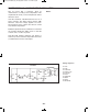
EXPERIMENT #70: OPERATIONAL AMPLIFIER COMPARATOR
Schematic
-89-
Wiring Sequence:
o 31-67
o 84-82-33-70-121
o 63-122
o 68-83-78
o 69-81-76
o 75-132
o 77-119-124
o 120-133
o 123-131
EP-130_62315RevC.qxp_EP-130_062812 6/23/15 11:17 AM Page 89