
Manual


-84-
N
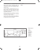
ow you will let one oscillator control another to
create an alarm. Here we have a multivibrator-type
oscillator controlling a pulse oscillator. The pulse
o
scillator produces frequency in the audible range
(the range that our ears can hear, about 20 to 20k
Hertz). The multivibrator circuit on the left side of the
schematic should look familiar. The multivibrator
commands the pulse oscillator by allowing current
to flow to the transistor base.
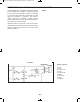
Build the experiment and press the key to hear the
alarm sound coming from the speaker. You hear the
alarm resonate turning on and off as the pulse
oscillator turns on and off.
This intermittent sounding alarm is more beneficial
than a continuous tone, because it is more
noticeable. You can experiment with this experiment
by varying the values of the 22kW, 47kW, and
100kW resistors, and the 0.02mF capacitor.
N
otes:
EXPERIMENT #66: PULSE ALARM
Wiring Sequence:
o 1-29
o 2-30
o 3-103-109
o 4-42-45-138
o 5-47-110
o 40-113-87
o 41-112-75
o 43-111-85
o 44-114-73-89
o 46-104-90
o 76-86-88-74-48-124
o 119-137
o 121-122
Schematic
EP-130_62315RevC.qxp_EP-130_062812 6/23/15 11:17 AM Page 84