
Manual


-80-
This circuit is an oscillator with a slow frequency,
and you can see the LED lighting and turning off.
T
he off time is longer than the on time, so you
o
bserve short pulses of light with long periods
between them. The wiring sequence below will
make the decimal point light, however you can light
any part of the LED display.
This type of circuit is known as a sawtooth wave
oscillator, because the electrical waveform of the
signal looks like a sawtooth pattern between two
voltage values. The signal alters as the LED lights
and turns off. Shorter pulses are generated when
the output from the emitter of the PNP transistor
supplies the base current to the NPN transistor (as
in this circuit).
Try experimenting by altering the value of the 3.3mF
capacitor to 10mF. You can also differ the 1kW
resistor and alter the 470kW resistor to 220kW. The
rate of charge and discharge of the capacitor
controls the frequency of this oscillator. Changing its
value or the values of the resistors that supply
current to the capacitor alters the frequency.
Notes:
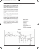
EXPERIMENT #62: DECIMAL POINT STROBE LIGHT
Schematic
Wiring Sequence:
o 47-40-25-89
o 41-46
o 42-76
o 90-112-48-120
o 75-94-111
o 93-119-24
EP-130_62315RevC.qxp_EP-130_062812 6/23/15 11:17 AM Page 80