
Manual


-75-
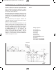
Does anything look familiar about the schematic for
this project? This circuit uses an R-S flip-flop circuit
m
ade from NAND gates, comparable to the circuit in
e
xperiment 38 (R-S Flip-Flop using TTL).
Once you have finished building this project, set the
switch to position A and press the key. A sound
should result from the earphone. Try pressing the
key multiple times. This should not alter the sound
in your earphone. Now move the switch to position
B and push the key one more time. What occurs
now?
Circuits like this are used in alarms. Since intruders
usually can’t figure out how to make them stop, they
are extremely useful.
Notes:
EXPERIMENT #58: SET/RESET BUZZER
Wiring Sequence:
o 13-77-75-49-45
o 14-119
o 40-109-85
o 41-106-79
o 42-55-51
o 43-105-81
o 50-78-131
o 52-53
o 54-76-133
o 132-138
o 44-110-71-87
o 121-137-62-60-59-57-56-80-82-86-72
o 88-EARPHONE
o 82-EARPHONE
o 13-14 (POWER)
Schematic
EP-130_62315RevC.qxp_EP-130_062812 6/23/15 11:17 AM Page 75