
Manual


-74-
C
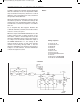
arefully compare the schematic for this experiment
with the schematic for the last experiment. While
they are similar in many ways, but there’s a critical
d
ifference. Can you find what it is? Can you tell how
the operation will be different?
Attach the earphone to Terminals 13 and 14 and set
the switch to position A. You will hear nothing in the
earphone but you should find that LED 1 lights up.
You will hear a sound in the earphone once LED 1
turns off.
Try to decipher why this happens. Examine the
schematic and when you think you have the answer,
read on to check your guess.
When the output of the NAND multivibrator is 0, the
voltage at the junction of springs 42-58-33 is low.
This allows current to flow through LED 1, but the
transistor multivibrator won’t work because there is
no voltage to its left transistor. When the output of
the NAND multivibrator is 1, the voltage at the
springs 42-58-33 junction is high. This prevents
current from flowing through LED 1, but the
transistor multivibrator now works because there is
voltage to its left transistor, and this multivibrator
controls the earphone sound.
N
otes:
EXPERIMENT #57: ANOTHER LED BUZZING
Wiring Sequence:
o 131-45-31-49
o 116-76-56-57-55
o 40-109-85
o 42-58-33
o 43-105-81
o 50-51-77-115
o 52-53-54-75-78
o 72-59-60-62-80-82-86-121
o 119-132
o 44-110-71-13-EARPHONE
o 41-106-79-14-EARPHONE
Schematic
EP-130_62315RevC.qxp_EP-130_062812 6/23/15 11:17 AM Page 74