
Manual


-72-
T
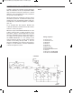
his is another type of one-shot circuit; in this project
you hear the effects of the multivibrator. From the
schematic you can see that this experiment uses a
c
ombination of simple components and digital
electronics. Once you press the key, the 100mF
capacitor is charged and lets the NPN translator in
the left corner of the schematic operate. You can
observe that the collector of this transistor serves as
both inputs for the first NAND gate.
The digital portion in the middle controls the PNP
transistor on the right side of the schematic. To turn
the power on, set the switch to A. You hear a sound
from the speaker when the output of the first NAND
is 1, and the multivibrator is enabled.
This sound will continue until the 100mF capacitor
discharges, preventing the first transistor from
operating. When the output of the first NAND
becomes 0, the multivibrator shuts off. With the
component values as shown in the schematic, the
sound will last for about 10 seconds. Try substituting
the 22kW with the 47kW or the 100kW resistor and
see what occurs.
Part B: press the key and release it. When the
sound stops, remove the wire between springs 52
and 54. What happens? Can you explain why?
N
otes:
EXPERIMENT #55: TRANSISTOR TIMER USING TTL
Wiring Sequence:
o 1-29
o 2-30
o 3-41
o 5-59-60-62-48-116-121
o 40-82
o 79-49-42-131-138
o 46-86
o 47-50-51-80
o 52-54
o 53-77-111
o 55-57-56-75-78
o 58-76-81-112
o 85-115-137
o 119-132
Schematic
EP-130_62315RevC.qxp_EP-130_062812 6/23/15 11:17 AM Page 72